HYDRAULIC AND AIR SYSTEMS 2250 SERVICE/MAINTENANCE MANUAL
2-32
Published 07-19-16, Control # 249-01
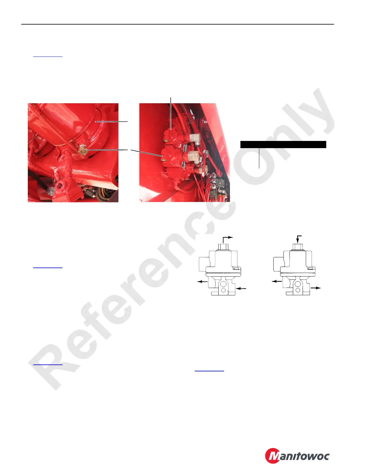
BREATHER VENT MAINTENANCE
See Figure 2-36 for the following procedure.
The solenoid valves (2) on the left side of the rotating bed
and the brake chambers (1) at the drum brakes are equipped
with breather vents (3).
Inspect the breather vents weekly to make sure they are not
obstructed by any debris. If necessary, remove and clean (or
replace) them as needed.
SOLENOID VALVE MAINTENANCE
Operation
Normally Closed
See Figure 2-37 for the following.
Pressure is applied to inlet port P. With the valve de-
energized, air at port P is sealed off by the force of the
plunger return spring and the seal in the plunger assembly.
Cylinder port A is open to exhaust port E.
When current is applied to the coil, the plunger assembly
moves to open inlet port P to cylinder port A. Exhaust port E
is sealed off by the plunger assembly.
Normally open operation is the opposite of normally closed
operation.
Air Line Connection
See Figure 2-37 for the following.
The solenoid valve has three ports identified as follows:
• P = Inlet from control valve
• A = Outlet to cylinder
• E = Exhaust
For normally closed operation, the air lines must be
connected to the valve ports.
For normally open operation, the air lines must be connected
to the valve ports.
NOTE: Improper connection of the air lines will cause
improper system operation.
Electrical Connection
See Figure 2-38 for the following procedure.
If the coil housing is located in an inconvenient position, it
may be oriented in 90-degree steps. For 90 degrees, remove
the two housing screws and relocate the two housing plate
screws. For 180 degrees, remove only the two housing
screws. Reinstall the screws after orientation.
FIGURE 2-36
Item Description
1 Brake Chamber (qty varies)
2 Solenoid Valve (qty varies)
3 Breather Vent (qty varies)
M100590
M100591
1
3
2
FIGURE 2-37
S126
S125
Normally Closed
Normally Open
E
A
P
E
A
P

 Loading...


