INTRODUCTION 2250 SERVICE/MAINTENANCE MANUAL
1-92
Published 07-19-16, Control # 249-01
Mast Stop
Mast Stop Cylinders
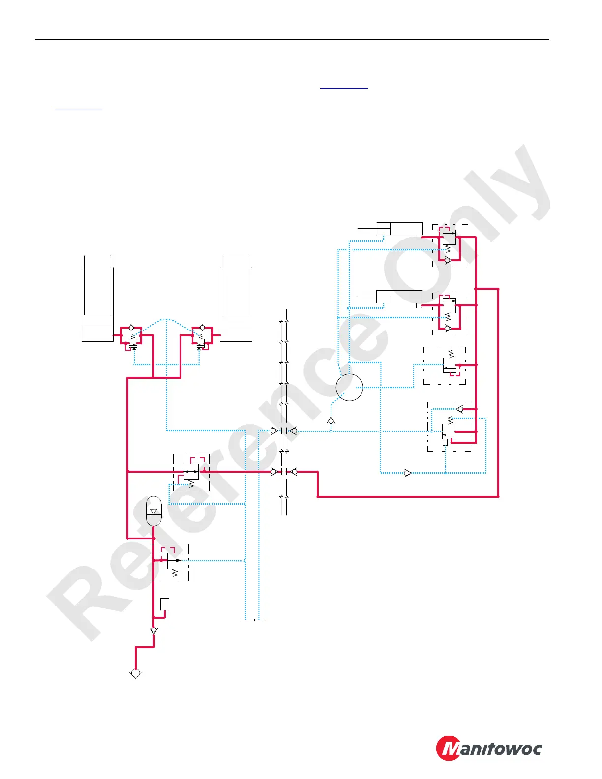
See Figure 1-60 for the following.
The mast stop cylinders are connected to the mast and
contact the gantry pins to stop the mast when at or near
maximum mast angle. The hydraulically filled cylinders act
as shock absorbers to cushion the mast as it contacts the
gantry. After a certain distance, the mast stop cylinders
bottom out to stop the mast’s travel.
Mast Stop System Operation
See Figure 1-60 for the following.
The crane’s auxiliary pump supplies pressurized hydraulic
fluid to the mast stop cylinders and jib strut cylinders at
152 to 200 bar (2,200 to 2,900 psi). The system pressure is
monitored and controlled by the mast accumulator pressure
sensor. From the crane’s auxiliary pump, pressurized
hydraulic fluid goes through the quick disconnect at the mast
butt, through an in-line check valve, and into an accumulator
mounted on the mast butt.
RM-16
179 bar (2,600 psi)
(2,400 psi)
Mast Stop
Cylinders
Jib Strut
Reservoir
Jib Strut
145 bar (2,100 psi)
145 bar (2,100 psi)
Relief Valve
Relief Valve
Cylinders
FIGURE 1-60
Boom
Mast
(2,200 psi)
Accumulator
T
Pressure
Sender
Accumulator
Mast
166 bar
207 bar (3,000 psi)
152 bar

 Loading...


