Manitowoc Published 07-19-16, Control # 249-01 8-1
2250 SERVICE/MAINTENANCE MANUAL UNDERCARRIAGE
SECTION 8
UNDERCARRIAGE
TURNTABLE BEARING BOLT TORQUE
Installing the Turntable Bearing
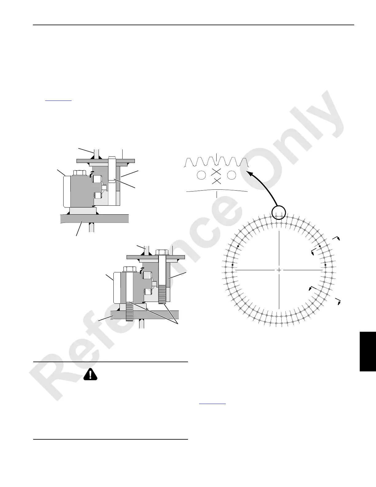
See Figure 8-1 for the following.
The outer ring of the turntable bearing must be properly
mounted to allow the rotating bed to be parked in line with the
crawlers or the carrier.
The gear tooth valley marked XX in the outer ring must be
mounted on the longitudinal centerline at the front or rear of
the carbody or carrier as shown.
Four dowel pins are installed in the inner ring as shown in
View A-A. Use the pins to align the upper adapter with the
inner ring.
Torque Requirements
Lubrication
Before installing the turntable bearing bolts, lubricate the
threads of each bolt with Never-Seez (MCC 361010) or an
equivalent antiseizing lubricant.
Torque Sequence
Tighten the bolts in the numbered sequence given in
Figure 8-1
.
Torque Values
When used turntable bearing bolts are installed, tighten each
bolt to 2 848 Nm (2,100 lb-ft).
FIGURE 8-1
59
1
23
51
11
43
19
35
7
55
27
47
15
39
31
58
22
50
10
42
18
34
54
26
46
14
38
30
60
24
52
12
44
20
36
8
56
28
48
16
40
32
57
21
49
9
41
17
33
53
25
45
13
37
29
6
5
4
3
2
Longitudinal Centerline at
the Front or the Rear of
the Carbody or the Carrier
Upper
Adapter
Outer
Ring
Inner
Ring
Dowel Pin
(4 each)
Upper
Adapter
Outer
Ring
Carbody, Carrier,
or Turret
Inner
Ring
Bolts with Hardened
Washers (60 for each ring)
B
B
A
A
Carbody, Carrier,
or Turret
View A-A
View B-B
A473
WARNING
Turntable Bearing Hazard!
Death or serious injury may occur due to loose or
improperly tightened bolts. The bolts and/or the turntable
bearing can fail, possibly allowing the rotating bed to
break away from the carbody, carrier, or turret.
Make sure that all bolts are tightened to the proper torque
specification.

 Loading...


