BOOM 2250 SERVICE/MAINTENANCE MANUAL
4-4
Published 07-19-16, Control # 249-01
Adjusting the Minimum Automatic Boom Stop
See Figure 4-2 for the following procedure.
NOTE: The slots in the actuator (3b) allow the minimum
boom angle to be adjusted to any angle between 4°
above and 4° below horizontal.
1. If necessary, adjust the limit switch (2b) in relation to the
actuator bracket (4) as shown in View B. Make sure the
mounting hardware is tight after making the adjustment.
2. Loosen the capscrews (5) that secure the actuator to the
actuator bracket.
3. Cut and remove the wire and lead seal from the dowel
pin (6). The dowel pin prevents the actuator from moving
after the actuator position is set. Remove the dowel pin.
4. Rotate the actuator clockwise so it does not contact the
limit switch roller when step 5
is performed.
5. Lower the boom to the desired minimum angle.
6. Rotate the actuator against the limit switch roller until the
limit switch clicks open. Hold the actuator in this position
(see View A).
7. Check the position of the actuator with relation to the
actuator bracket as instructed (see View C).
8. Tighten the capscrews to secure the actuator to the
actuator bracket.
9. Verify the adjustment as follows:
a. Raise the boom several degrees above the desired
minimum angle.
b. Slowly lower the boom.
c. The boom should stop at the desired minimum
angle. If it does not stop at the desired angle:
- Stop lowering the boom.
- Raise the boom several degrees above the
desired minimum angle.
- Repeat step 4
through step 9.
10. Use a new dowel pin, wire, and lead seal. Drill a new
hole to seal the adjustment as shown in View D.
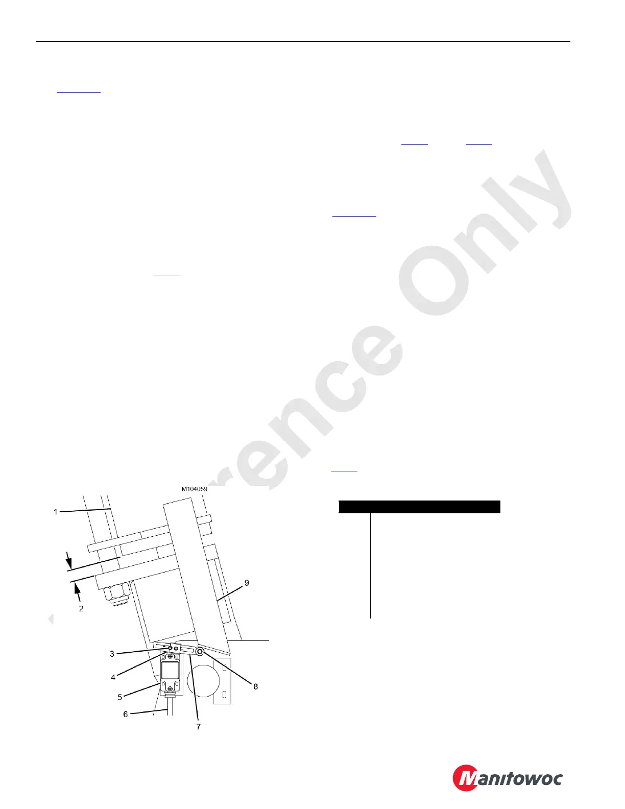
SETUP BOOM STOP ANGLE
See Figure 4-3 for the following procedure.
Perform the following steps when the crane is in Setup mode
and rigged only with the boom butt.
1. Loosen the setscrew (4) in the limit switch lever (7), so
the lever is free to rotate on the shaft (3).
2. Raise the boom butt until the physical boom stop (1) is
25 mm (1 in) (2) from bottoming out as shown. The
boom angle will be at approximately 89
°.
3. Hold the roller (8) on the lever against the actuator (9).
Adjust the length of the lever, if necessary.
4. Turn the limit switch shaft clockwise (as viewed from the
front of the switch) until the switch clicks open. Hold the
switch in this position.
5. Securely tighten the setscrew in the lever.
6. Lower the boom butt several degrees.
7. Slowly raise the boom butt.
8. The boom butt must stop at the position specified in
step 2
. If not, repeat this procedure.
NOTE: Standard mounting shown. Mounting is raised
approximately 0,61 m (2 ft) when equipped with
the fold-under luffing jib.
Item Description
1 Physical Boom Stop (left side)
2 25 mm (1 in)
3Shaft
4 Setscrew
5 Limit Switch
6 Cable to Air Valve Junction Box
7 Limit Switch Lever
8Roller
9 Actuator
FIGURE 4-3

 Loading...


