Manitowoc Published 07-19-16, Control # 249-01 5-5
2250 SERVICE/MAINTENANCE MANUAL HOISTS
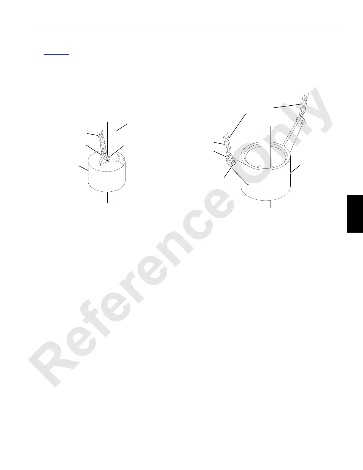
Installation
See Figure 5-3 for installation of the weights.
The block-up limit control must be installed according to the
assembly drawing.
Securely fasten the electrical cords to the boom and jib with
the metal straps and nuts provided.
When equipped with more than one block-up limit switch,
wire the limit switches in series.
Connect the electrical wires to the normally closed contacts
inside each limit switch.
FIGURE 5-3
A1050
Lower Boom Point (multiple part),
#132 or #140 Fixed Jib (4 part),
Extended Upper Boom Point (4 part), or
Lower Luffing Jib Point (multiple part)
#132 or #140 Fixed Jib (1 to 3 part),
Standard or Extended Upper Boom Point (1 to 3 part),
Upper Luffing Jib Point (1 part)
See Load Block Reeving in Section 4 of the Operator Manual
for the Suggested Location of the Weight.
Dead End Load Line or
Slowest Live Line
Connecting
Pin
Chain
Shackle
Weight
Chain
Shackle
Connecting
Pin
Weight
Two Chains Prevent
Weight from Turning
 Loading...


