Manitowoc Published 07-19-16, Control # 249-01 2-33
2250 SERVICE/MAINTENANCE MANUAL HYDRAULIC AND AIR SYSTEMS
Maintenance
Troubleshooting
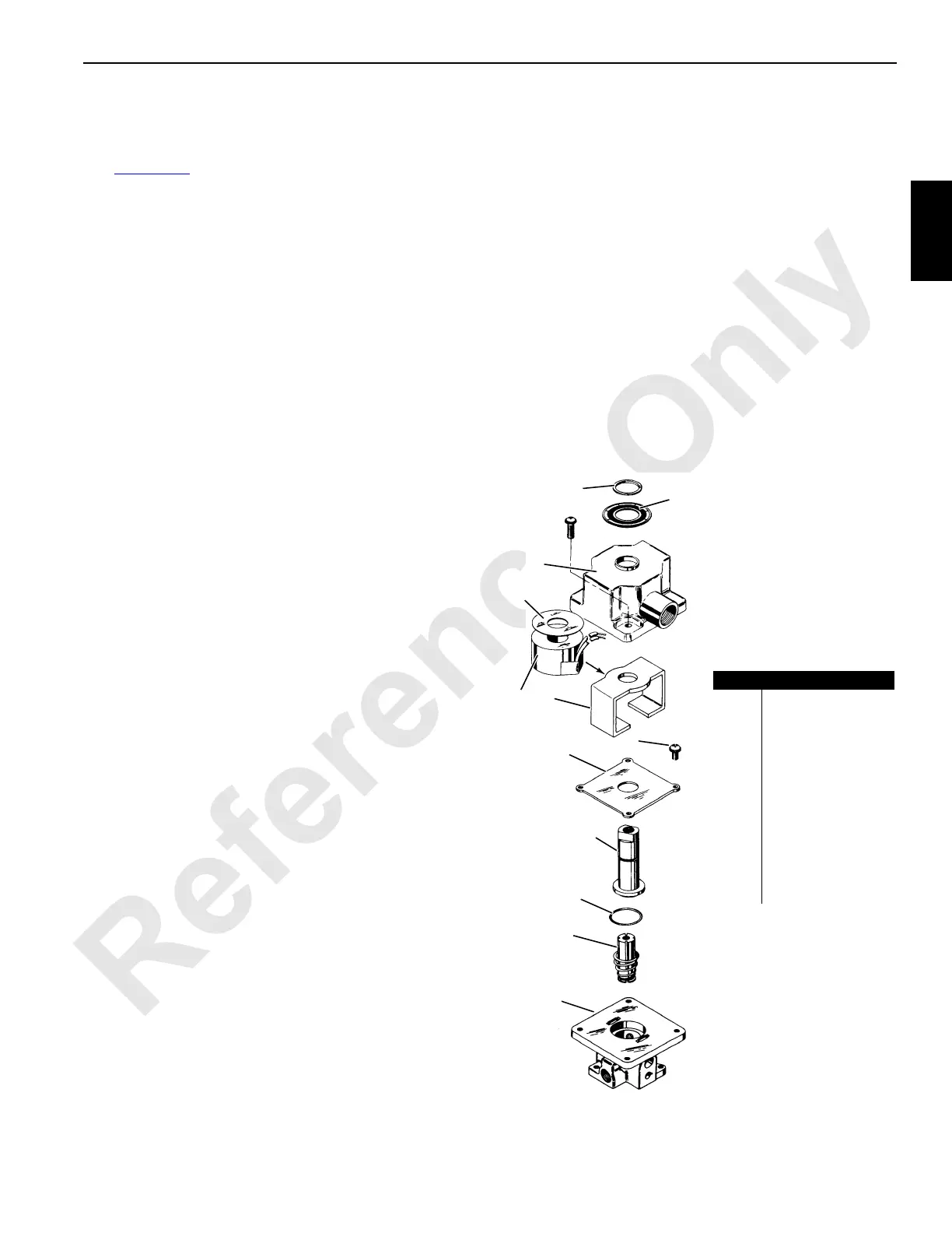
See Figure 2-38 for the following procedures.
If the valve fails to operate at all, check the coil (5) for
shorted or open turns. Also check the supply current. See
the following troubleshooting topics if the coil is not
damaged.
Troubleshooting—External Leakage
If leakage occurs around the sleeve (9), the metering pins, or
the manual override stem, the O-rings (10) should be
removed and inspected for imperfections.
Troubleshooting—Sticking or Internal Leakage
If the valve leaks internally or the plunger (11) sticks in the
energized position, examine the soft inserts in the plunger
ends or inside the sleeve (9) for excessive dirt or wear. If the
inserts show considerable wear, the plunger should be
replaced.
Troubleshooting—Noise
If the valve develops a loud buzzing noise, check the voltage
and pressure to determine if they correspond to the
nameplate (2) rating. Examine the inside of the sleeve (9)
and the upper portion of the plunger (11). Remove all foreign
matter embedded in these parts. Do not damage the sleeve
seat.
NOTE: Do not expose the plunger or O-rings (10) to any
type of commercial cleaning fluid. Clean the
plunger and O-rings with a mild soap-and-water
solution.
Disassembly
1. Shut off pressure and electricity to the valve. The valve
does not need to be removed from the line.
2. Remove the screws from the housing (3).
3. Remove the housing from the valve assembly.
4. Remove the yoke (6) and coil (5) with an upward
twisting motion.
5. Remove the screws (7) that hold the housing plate (8) to
the body (12).
6. Remove the housing plate, sleeve (9), and plunger (11).
Reassembly
1. Place the housing plate (8) over the sleeve (9).
2. Apply a light oil to the O-ring (10) flange seal. Always
assemble the O-ring to the sleeve before inserting in
valve bodies.
3. Make sure the plunger (11) and the return spring are in
place and then push the sleeve, along with the housing
plate, down in place on the body (12) with a slight
twisting motion.
4. Hold the housing plate down and replace the screws (7).
Tighten the screws to 2 ± 0,3 Nm (18 ± 3 in-lb). Place
these screws so they give the desired orientation of the
housing later in reassembly.
5. Apply pressure to the port that leads to the body
chamber and check for leakage around the flange seal.
If the valve has a sleeve port, cap the port at the top of
the sleeve to perform this test.
6. Check for leakage by applying a soap-and-water
solution to the joint and watch it for air bubbles.
7. Once the housing plate is secure, push the yoke (6) and
coil (5) over the sleeve with a slight twisting motion.
8. Install the housing with two screws. Tighten the screws
to 2 ± 0,3 Nm (18 ± 3 in-lb).
9. Repeat the internal leakage check.
FIGURE 2-38
S127
Item Description
1 Nameplate Retainer
2 Nameplate
3 Housing
4 Coil Washer
5Coil
6Yoke
7 Screw (qty 2)
8 Housing Plate
9Sleeve
10 O-ring
11 Plunger
12 Body
1
2
3
4
5
6
7
8
9
10
11
12
 Loading...


