HYDRAULIC AND AIR SYSTEMS 2250 SERVICE/MAINTENANCE MANUAL
2-8
Published 07-19-16, Control # 249-01
4. Tighten the jam nut. When the fitting is properly installed,
the O-ring will completely fill the seal cavity and the
washer will be tight against the spot face (View B).
Table 2-4. Straight Thread Leakage
ORS
®
Connection
NOTE: ORS
®
is the registered trademark for a face-type
seal manufactured by Aeroquip Corporation.
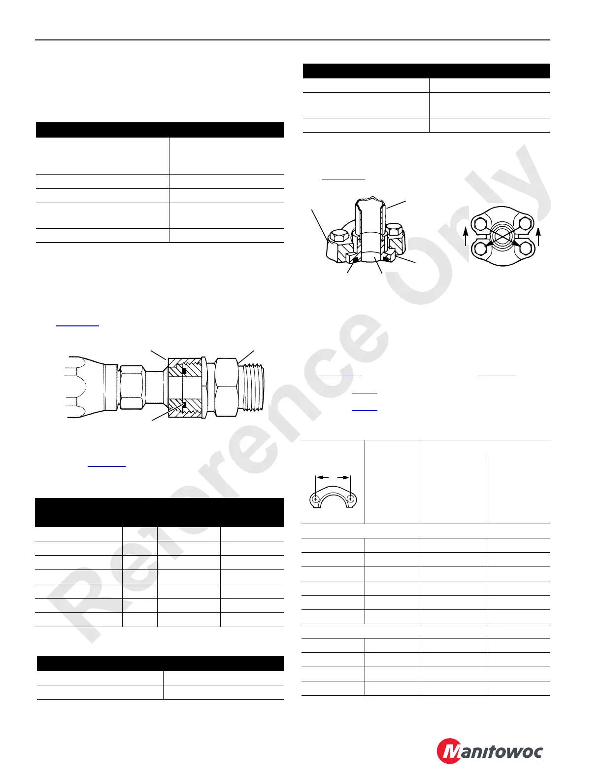
1. Lubricate and install the O-ring in the adapter groove
(Figure 2-7
).
2. Lubricate the threads. Tighten the nut to the torque value
given in Table 2-5
.
Table 2-5. ORS
®
Assembly Torque
Table 2-6. ORS
®
Leakage
Split Flange Connection
1. Lubricate and install the O-ring in the shoulder groove
(Figure 2-8
).
2. Align the shoulder with the port and assemble the
flanges over the shoulder.
NOTE: The bolts used must be grade 5 or better. A grade 5
bolt has three dashes in its head.
3. Snug the bolts in a diagonal manner as shown in
Figure 2-8
to 1/3 of the torque given in Table 2-7.
4. Repeat step 3
to 2/3 of the final torque.
5. Repeat step 3
to the final torque.
Table 2-7. Split Flange Assembly Torque
Cause Cure
Jam nut and washer not
backed up at assembly,
causing O-ring to be pinched
Replace O-ring and tighten
fitting properly
O-ring cut Replace
O-ring wrong size Replace with proper size
Sealing surfaces are scratched
or gouged
Repair if possible or
replace damaged parts
Sealing surfaces dirty Clean and lubricate
Nut Size
(inch across flats)
Fitting
Size
Torque
Nm in-lb
5/8 -04 14 to 16 120 to 145
13/16 -06 23 to 28 203 to 245
15/16 -08 43 to 53 380 to 470
1-1/8 -10 62 to 77 550 to 680
1-3/8 -12 86 to 107 763 to 945
1-5/8 -16 125 to 142 1110 to 1260
1-7/8 -20 170 to 190 1500 to 1680
Cause Cure
Nut loose Tighten to proper torque
O-ring cut Replace
FIGURE 2-7
S105
Nut
Adapter
O-ring
O-ring wrong size Replace with proper size
Sealing surfaces gouged or
scratched
Repair/replace damaged
parts
Sealing surfaces dirty Clean and lubricate
Dimension A
inch
Flange
Size
Torque
Nm in-lb
Standard Pressure Series
1-1/2 -08 20 to 25 175 to 225
1-7/8 -12 25 to 40 225 to 350
2-1/16 -16 37 to 48 325 to 425
2-5/16 -20 48 to 62 425 to 550
2-3/4 -24 62 to 79 550 to 700
3-1/16 -32 73 to 90 650 to 800
High Pressure Series
1-9/16 -08 20 to 25 175 to 225
2 -12 34 to 45 300 to 400
2-1/4 -16 57 to 68 500 to 600
2-5/8 -20 85 to 102 750 to 900
Cause Cure
FIGURE 2-8
S104
1
2
3
4
S101
Flange
Tube
Shoulder
O-ring Port
 Loading...


