Manitowoc Published 07-19-16, Control # 249-01 1-79
2250 SERVICE/MAINTENANCE MANUAL INTRODUCTION
Tongue Cylinder
See Figure 1-49 and Figure 1-50 for the following.
The tongue cylinder aligns the wheeled counterweight trailer
for attachment to the crane and levels the counterweight tray
before positioning the steering wheels. The wheeled
counterweight tray pins must be in the proper position for
leveling. See Section 4 of Operator Manual for pin positions.
After the wheeled counterweight trailer is leveled, return the
tray pins to the operating position.
With the engine running, power is available to the MAX-ER’s
remote switch assembly when the power cable (W28) is
plugged into the receptacle on the left side of the
counterweight trailer. When the power button on MAX-ER’s
remote switch assembly is pressed, power is enabled to
operate the tongue cylinder switch. The switch is spring-
returned to the OFF position. In the OFF position, the tongue
cylinder solenoid valve is “motor spooled” with both cylinder
ports and the tank port connected when not enabled. This
prevents premature opening of the counterbalance valves at
the cylinder.
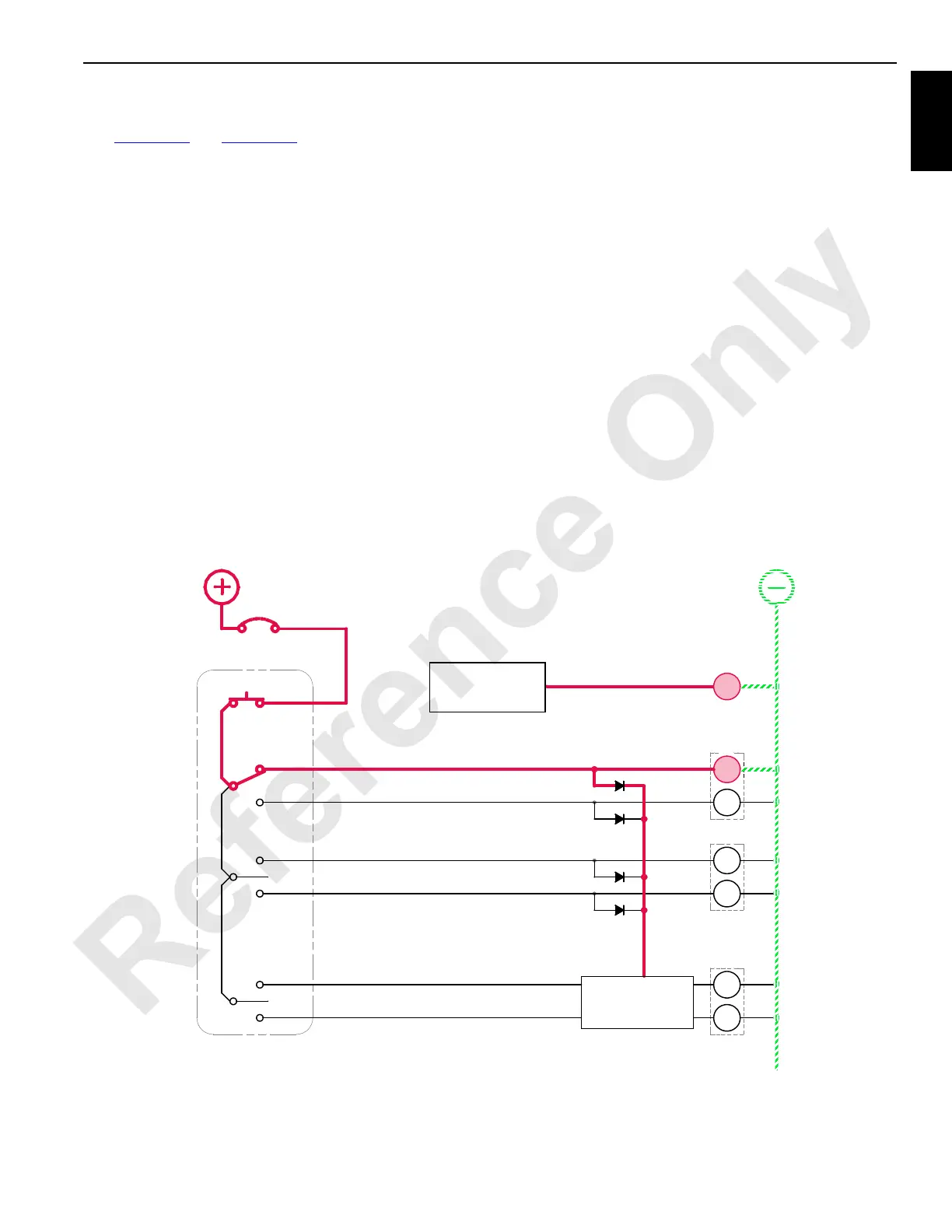
Tongue Cylinder Extend
When the power button is pressed and the tongue cylinder
switch is enabled and held in the UP (extend) position, an
input signal is sent to the programmable controller (PC). A
12 V output signal from the PC enables the tongue cylinder
extend solenoid HS-50. Internal pilot supply pressure of
14 bar (200 psi) enables the selected spool to shift the
tongue cylinder solenoid valve. The crane’s PC sends an
output signal to shift the crane’s auxiliary system disable-
relief valve HS-12 to block the valve’s bypass. Accessory
system pressure increases to operate the accessory items.
Accessory system fluid enters the MAX-ER’s accessory
valve and flows to the free-flow check valve section of the
counterbalance valve, entering the piston end of the tongue
cylinder, and starts to extend the tongue cylinder. Fluid from
the rod end of the cylinder is blocked by the free-flow check
valve section of the counterbalance valve and flows through
the flow-restraining section that has a relief setting of 193 bar
(2,800 psi). Return hydraulic fluid then exits the
counterbalance valve and passes through the MAX-ER’s
accessory valve before returning to the crane’s hydraulic
tank through the return line. Release the tongue cylinder
switch to the OFF position to lock the tongue cylinder in
position.
56MB
56MA
89H4
55MB
55MA
Power
HS
51
HS
52
HS
53
HS
41
HS
40
89J4
89K4
0
15 Amp
CB
5A
8K
RM-05
Auxiliary System
Disable-Relief Valve
Tongue Cylinder Extend
Crane
Programmable
Controller
Tongue Cylinder Retract
Steering Pins Extend
Steering Pins Retract
Counterweight Strap
Cylinder Retract
Counterweight Strap
Cylinder Extend
MAX-ER 2000
Programmable
Controller
MAX-ER 2000 Remote
12
HS
HS
50
FIGURE 1-49
88S
 Loading...


