HYDRAULIC AND AIR SYSTEMS 2250 SERVICE/MAINTENANCE MANUAL
2-30
Published 07-19-16, Control # 249-01
AIR DRYER MAINTENANCE
Description
The air dryer is a filtering unit that cleans and dries the air
delivered to the air system by the air compressor.
The air dryer consists of a desiccant cartridge and a die cast
aluminum end cover secured to a cylindrical steel outer shell.
The end cover contains a check valve, a safety valve, three
threaded air connections, and the purge valve. The
desiccant cartridge and discharge check valve are the
screw-in type. Servicing the screw-in desiccant cartridge
requires removing the air dryer from the crane.
Replacing the Desiccant Cartridge
See Figure 2-35 for the following procedure.
NOTE: This procedure covers only the desiccant cartridge
replacement. Refer to the vendor manual for
replacement of any other air dryer components.
1.
Stop the engine.
2. Relieve all pressure in the reservoirs.
3. Tag and disconnect all air lines from the end cover (1).
4. Note the position of end cover ports relative to the crane.
5. Disconnect the wiring harness from the purge valve
assembly (2).
6. On a standard mounting bracket, loosen the
capscrew (3) and sleeve nut (4) that secure the
mounting strap (5) to the mounting saddle (6).
On a non-standard mounting bracket, loosen the
adjusting nut (7) and remove the mounting strap (8) and
isolator (9) from the upper bracket (10).
7. Remove the two end cover capscrews (11), lock
nuts (12), and special washers (13) that secure the end
cover to the lower mounting bracket (14).
NOTE: For installation purposes, tag the capscrews and
capscrew holes. These capscrews are longer than
the others, and it is important that they be
reinstalled in the correct places.
Retain the mounting hardware.
8. Remove the air dryer assembly (15) from the crane.
9. Remove the capscrews (16), lock nuts (17), and special
washers (18) that secure the end cover to the air dryer
housing (19).
10. Remove the air dryer housing from the end cover.
11. Remove the outer housing O-ring (20).
12. Remove the desiccant cartridge (21) from the end cover
by turning the cartridge counterclockwise.
NOTE: It is acceptable to use a strap or chain around the
cartridge to assist in removal. Make sure to place
the strap or chain 50 to 76 mm (2 to 3 in) away from
the end cover.
A significant amount of force may be required to
remove the cartridge.
13. Remove the desiccant cartridge O-ring (22).
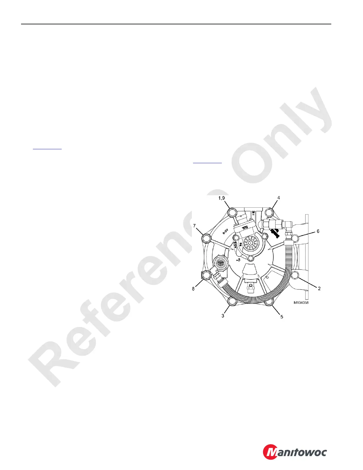
See Figure 2-34
for the following procedure.
Installation is the reverse of removal. When tightening the
capscrews that secure the air dryer housing to the end cover,
follow the pattern shown.
For operation, leak testing, disassembly and assembly,
cleaning, inspection, and preventive maintenance, see the
vendor manual and contact the Manitowoc Crane Care
Lattice Team.

 Loading...


