HYDRAULIC AND AIR SYSTEMS 2250 SERVICE/MAINTENANCE MANUAL
2-12
Published 07-19-16, Control # 249-01
REPLACING A PRESSURE SENDER
See Figure 2-16 for identification of the pressure senders.
General
These instructions must be followed to ensure safe removal
of faulty pressure senders and to ensure proper operation
after the installation of new pressure senders.
See Figure 2-16
for the following procedure.
NOTE: The replacement procedure is the same for all
pressure senders.
1. Lower all loads to the ground.
2. Move all control handles to OFF and park all crane
functions.
3. Stop the engine.
4. Place a suitable container under the pressure senders to
catch any oil leakage.
NOTE: Perform step 5
through step 9 only with faulty
pressure senders.
5. Disconnect the electric plug (2) from the pressure
sender.
6. Slowly loosen the pressure sender only enough to allow
any remaining pressure to exhaust.
7. Remove the pressure sender.
8. Install the new pressure sender and connect the electric
plug.
Pressure senders have pipe threads. Be sure to install
thread sealant.
9. Bleed the pressure sender as follows.
a. Connect a bleed line with a shut-off valve to the
gauge coupler (1) on the pressure sender manifold.
b. Open the valve in the bleed line and use a suitable
container to catch the oil flow.
c. With all control handles off, start the engine and
allow it to idle at 950 to 1,000 rpm.
d. Observe oil flowing from the bleed line.
e. Close the valve in the bleed line when clear oil flows
(no air bubbles in oil).
f. Stop the engine.
g. Remove the bleed line from the gauge coupler at
the pressure sender.
10. Calibrate the pressure sender.
CAUTION
High-Pressure Oil Hazard!
High-pressure oil can exhaust from the pressure sender
ports and cause minor to moderate injury.
Do not attempt to remove a pressure sender unless the
proper procedure is performed.
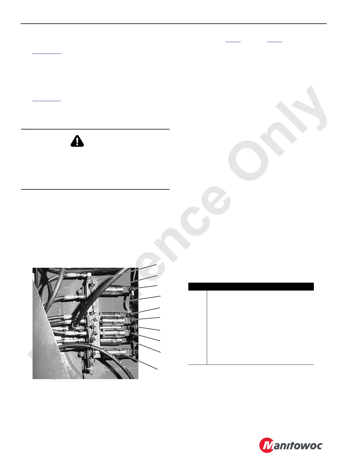
P930
2250 Left Inboard Side of Rotating Bed
(forward of pumps)
Item Description
1 Gauge Coupler (typical)
2 Electric Plug (typical)
3
Independent Luffing Hoist Pressure Sender
1
4 Right Travel System Pressure Sender
5 Left Travel System Pressure Sender
6 Load Drum Charge Pressure Sender
7 Load Drum System Pressure Sender
8 Boom Hoist System Pressure Sender
9 Swing Right System Pressure Sender
10 Swing Left System Pressure Sender
1
Optional
FIGURE 2-16
1
2
3
4
5
6
7
8
9
10
 Loading...


