INTRODUCTION 2250 SERVICE/MAINTENANCE MANUAL
1-68
Published 07-19-16, Control # 249-01
Air System Components
Counterweight/Backhitch Pins
See Figure 1-36 and Figure 1-41 for the following.
With the engine running, power is available to the setup
remote control when the cable is connected at the air valve
junction box on the left side of the rotating bed.
Counterweight/Backhitch Pins Extend
When the power button is pressed, power is enabled to
operate the counterweight upper pins switch, counterweight
lower pins switch, or backhitch pins switch.
Each pin switch is spring-returned to the (extend) position. In
this position, the counterweight upper pins extend normally
closed solenoid AS-5, the counterweight lower pins extend
normally closed solenoid AS-3, or the backhitch pins extend
normally closed solenoid AS-1 are enabled. Air flows
through the normally closed solenoid to the piston end of the
pin cylinders. The cylinders move the pins into engagement
while air from the rod end of the cylinders exhausts to the
atmosphere.
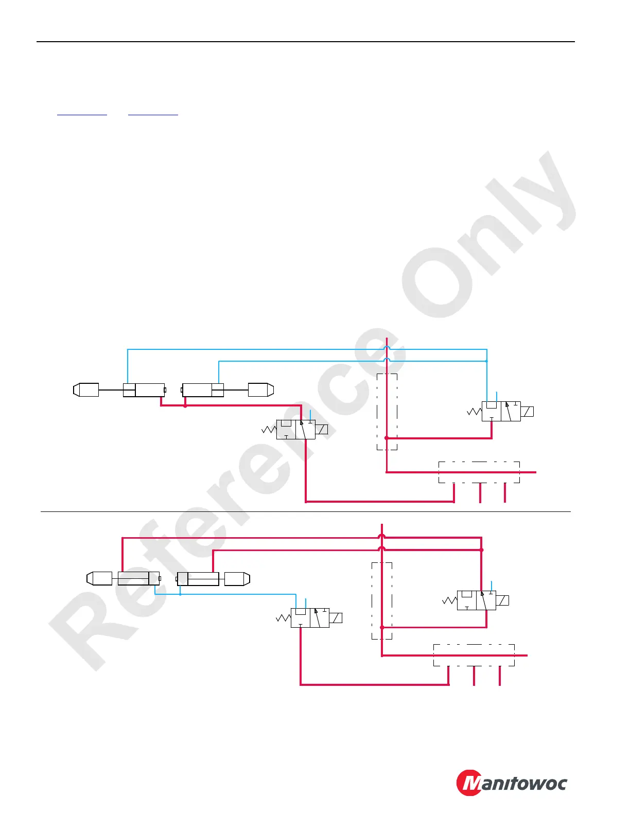
Counterweight/Backhitch Pins Retract
When the power button is pressed and the counterweight
upper pins switch is held in the UP (retract) position, an input
signal is sent to the programmable controller (PC). The PC
sends a 0 V output signal to disable the counterweight upper
pins normally closed solenoid AS-5 and a 12 V output signal
to enable the counterweight upper pins normally open
solenoid AS-6. Air then flows through the normally open
solenoid to the rod end of the counterweight upper pin
cylinders. The cylinders then retract to move the pins out of
engagement while air from the piston end of the cylinders
exhausts to the atmosphere.
When the power button or selected pin switch is released,
the PC sends a 0 V output signal to disable the
counterweight upper pins normally open solenoid AS-6 and
a 12 V output signal to enable the counterweight upper pins
normally closed solenoid AS-5.
RF-41
Main Air Manifold
Backhitch
Backhitch
Pin Cylinder
AS-2
AS-1
Pin Cylinders
P
P
E
A
E
A
Extend
Backhitch
Pin Cylinder
Retract
Air Manifold
RF-42
Main Air Manifold
Pin Cylinder
AS-6
AS-5
Pin Cylinders
P
P
E
A
E
A
Extend
Counterweight
Pin Cylinder
Retract
Air Manifold
Backhitch Pin Cylinders Extend
Counterweight Upper Pins Retract
Upper
Counterweight
Upper
Counterweight
Upper
FIGURE 1-41
 Loading...


