Manitowoc Published 07-19-16, Control # 249-01 10-45
2250 SERVICE/MAINTENANCE MANUAL TROUBLESHOOTING
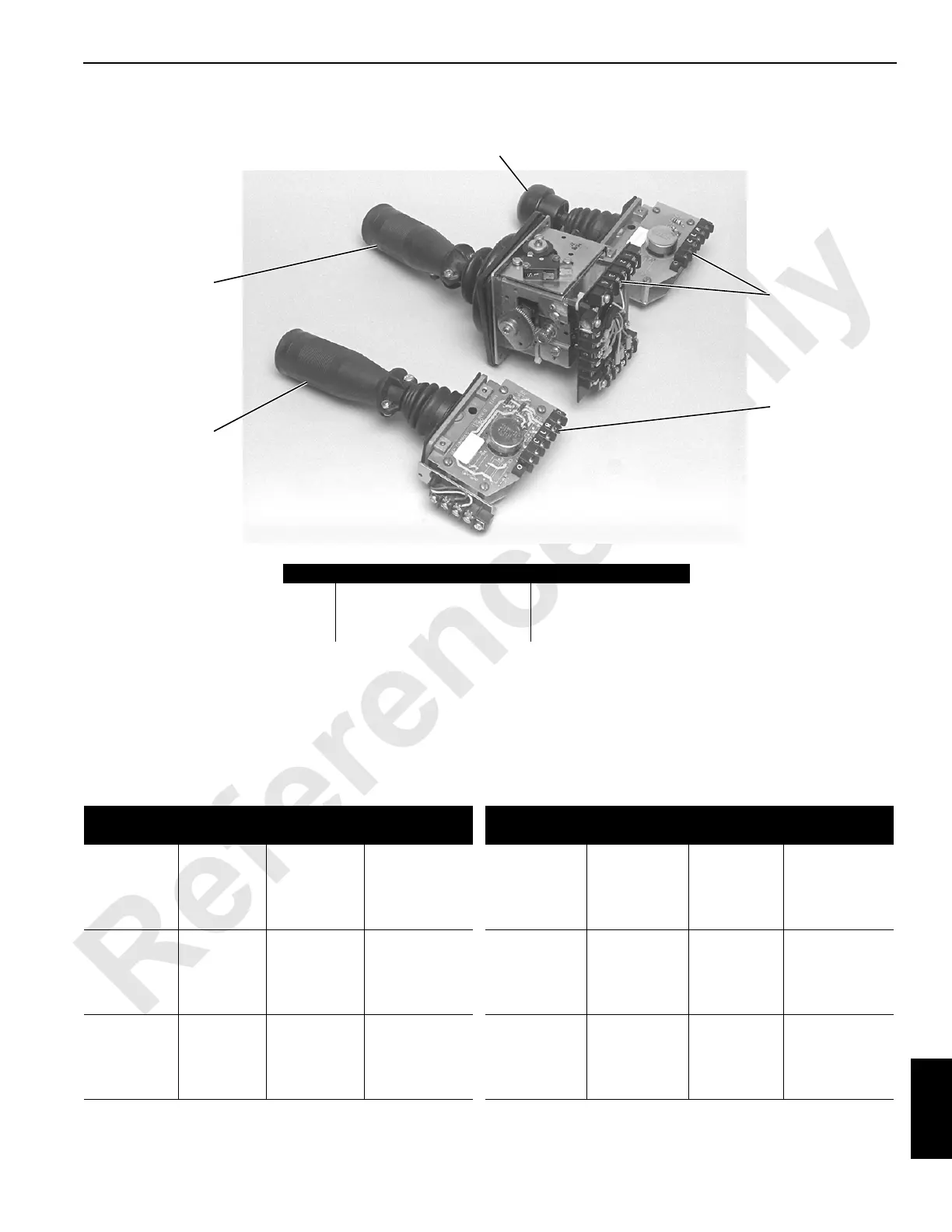
Test 12—Checking Voltage at the Control Handle
Perform the following procedure to determine the correct
voltages at the control handle.
1. The engine must be off and the power on, with all brakes
and locks engaged.
2. Enable the test control handle and measure the voltage
with a digital multimeter.
3. Place the positive lead on the test terminal (4) and the
negative lead on a grounded crane component or on
ground terminal R (5).vs
Voltages outside the normal range may indicate a problem
with the control handle, electrical circuit, or electrical
components.
P1524
1
2
3
4
5
FIGURE 10-13
Item Description Item Description
1 Load Drum Handle 4 Test Terminal
2 Boom/Swing Handle 5 Ground Terminal R
3 Crawler Handle
Hand
Controller
Test
Terminal
Wire No.
Acceptable
Voltage (DC)
Hand
Controller
Test
Terminal
Wire No.
Acceptable
Voltage (DC)
Swing
Left
Right
Center
3
4
87FA
0
85P
8S Brake
89B2 Brake
10
Ground
1.4 to 8.6
12
12
Left Travel
Left
Right
Center
87FA
0
84P
10
Ground
1.4 to 8.6
Boom Hoist
Left
Right
Center
1
2
87FA
0
82P
8A
82N
10
Ground
1.4 to 8.6
Ground
12
Front or
Right Rear
Load Drum
Left
Right
Center
1
2
87FA
0
80P
0
80N
10
Ground
1.4 to 8.6
Ground
12
Right
Travel
Left
Right
Center
3
4
87FA
0
83P
8D
89X
10
Ground
1.4 to 8.6
12
12
Rear or Left
Rear Load
Drum
Left
Right
Center
3
4
87FA
0
83P
0
81N
10
Ground
1.4 to 8.6
Ground
12
 Loading...


