Manitowoc Published 07-19-16, Control # 249-01 1-85
2250 SERVICE/MAINTENANCE MANUAL INTRODUCTION
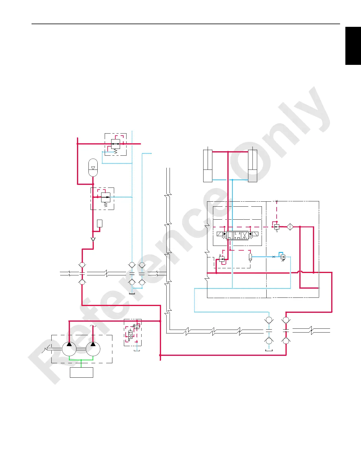
Steering Pin Cylinders Engage
When the steering pins switch is held in the DOWN (engage)
position, an input signal is sent to the PC. A 12 V output
signal from PC enables the steering pins engage solenoid
HS-52. Internal pilot supply pressure of 14 bar (200 psi)
enables the selected spool to shift the steering pins solenoid
valve.
The crane’s PC sends an output signal to shift the crane’s
auxiliary system disable-relief valve HS-12 to block the
valve’s bypass. Accessory system pressure increases to
operate the accessory items. Accessory system fluid enters
the MAX-ER’s accessory valve and flows to the piston end of
the steering pins to engage the pins at the right side and left
side steering arms. Return fluid from the rod end of the
cylinder passes through the MAX-ER’s accessory valve
before returning to the crane’s hydraulic tank through the
return line. Release the steering pins switch to lock the
steering arms in position.
(2,000 psi)
Wheeled Counterweight Trailer
X
XX
X
HS53
HS52
Disengage
Engage
Steering Pin
Cylinders
C2C1
13,8 bar
(200 psi)
RM-10
MAX-ER Accessory Valve
FIGURE 1-54
(2,200 psi)
Stop Cylinders
From Mast
Stop Cylinders
To Mast
Mast
Accumulator
T
To Jib Strut
Cylinders
Jib Strut
Cylinders
From
Pressure
Sender
Accumulator
Mast
(3,000 psi)
207 bar
138 bar
207 bar (3,000 psi)
152 bar
Accessory
To Crane
Crane
Manifold
Suction
Aux
Fan
Valves
HS12
Valve
Disable-Relie
f
Auxiliary System
 Loading...


