Manitowoc Published 07-19-16, Control # 249-01 1-23
2250 SERVICE/MAINTENANCE MANUAL INTRODUCTION
The auxiliary pump provides hydraulic fluid pressure for the
accessory valve’s operation. The fan pump provides fluid
requirements for the fan motors and pilot fluid pressure for
the accessory valve’s operation.
All the main pumps are variable-displacement, axial-piston
pumps that operate in a bi-directional closed-loop system.
Each pump contains the following:
• Charge pump
• Electrical displacement control (EDC)
• Cylinder block where pistons are positioned axially
around a drive shaft
• Charge-pressure relief valve
• Two multifunction (relief) valves
Each system pump has a gerotor-type charge pump that is
internally mounted on the end of each pump system’s
driveshaft. The charge pump draws fluid directly from the
suction manifold and delivers it to the closed-loop system at
a charge pressure of approximately 24 bar (350 psi). Charge
pressure depends on the engine’s load/speed, pressure-
relief valve settings, and hydraulic system’s efficiency.
When a system control handle is moved, the programmable
controller (PC) sends a variable plus or minus 0 to 2.8 V
output to the pump’s EDC as required for the handle’s
command direction. The EDC tilts the swashplate to stroke
the pump in the command direction. The pump’s pistons
move within the cylinder block as the block rotates. The
longer stroke of each piston draws in return fluid from the
system’s motor. As the stroke shortens, hydraulic fluid is
pushed out of the pump piston cylinders into hydraulic piping
to the motor.
Hydraulic fluid displaced by the motor returns through the
piping to the inlet side of the system pump. The swashplate’s
tilt angle determines the volume of fluid that can be pumped
to the motor. Increasing the swashplate’s tilt angle increases
the piston stroke length, allowing more fluid to be pumped to
the motor.
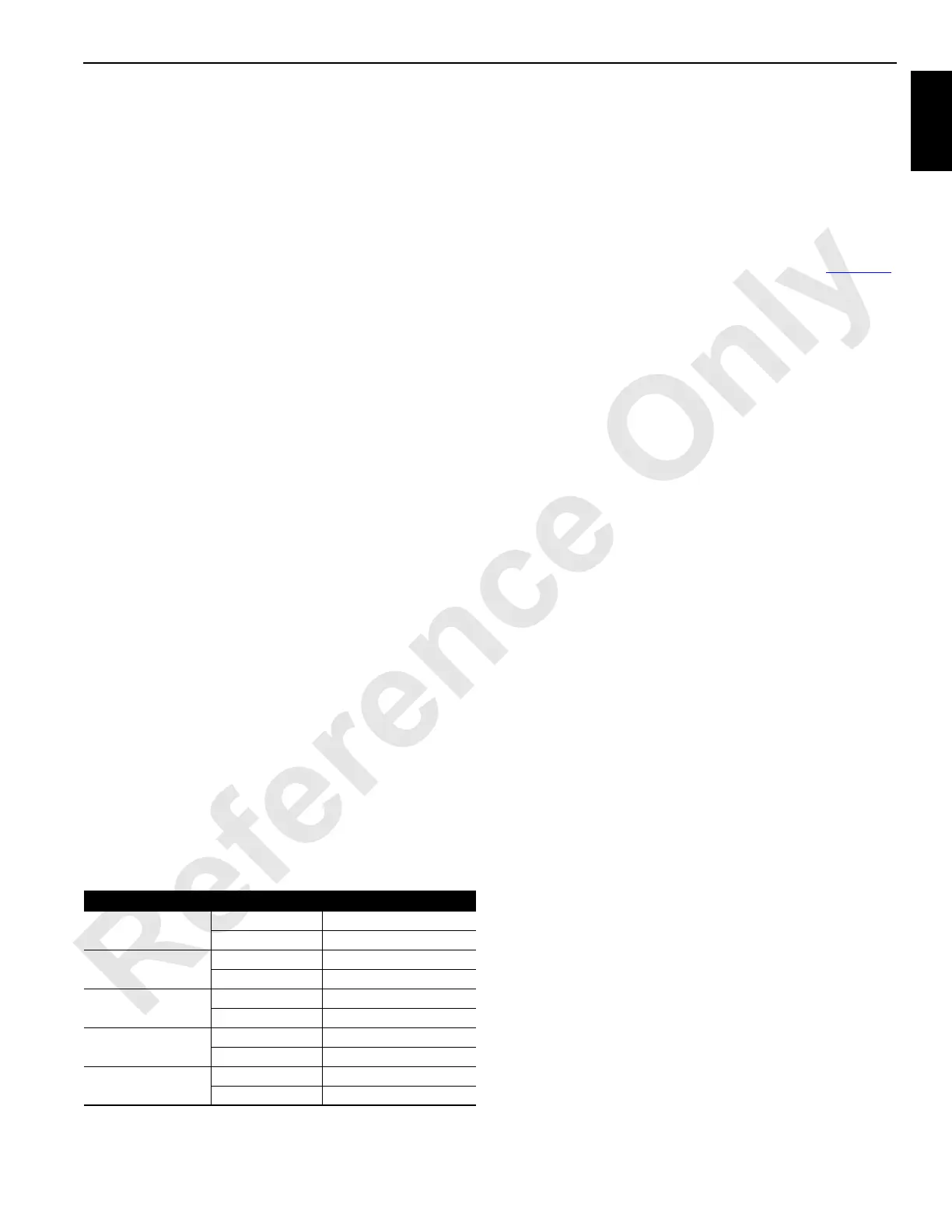
Table 1-2. Malfunction Valve Pressure Limit Pressure
Each pump has two multifunction valves that consist of a
system-relief valve and a charge flow make-up check valve.
The pump’s system multifunction valves control the
maximum system pressure and protect each pump’s system
from damage by limiting pressure spikes in each operating
direction. When preset loop system pressure is reached, the
multifunction valves limit system pressure by de-stroking the
pump or transferring fluid from the high-pressure side to the
low-pressure side. The maximum pressure setting of the
multifunction valves for each pump is listed in Ta bl e 1- 2
.
Limits should not be reached unless there is a failure in the
system.
Charge Pressure
Charge pressure in each closed-loop system is preset at
approximately 24 bar (350 psi) with a relief valve in the
charge pump. If the charge pressure is set too high, the
hydraulic system could be damaged. Charge pressure must
be at the preset value as lower pressures can cause a
slowing or stopping of operation. When a system control
handle is in the neutral position, the digital display screen
indicates system charge pressure.
If the boom/luffing jib charge pressure system drops, the
brake begins to apply at approximately 20 bar (295 psi) for
the boom hoist and 18 bar (260 psi) for the luffing jib. The
brakes are fully applied at 15 bar (219 psi) for the boom hoist
and 10 bar (140 psi) for the luffing jib.
Hydraulic Motors
See Sauer-Sundstrand Service Manual or Rexroth Service
Manual for a description of a hydraulic motor.
Variable-displacement low-torque/high-speed, bent-axis
piston hydraulic motors are used in the travel, boom hoist,
and load drum systems. The swing system motor is a fixed-
displacement, low-torque/high-speed, bent-axis piston
hydraulic motor. Each motor contains a cylinder block,
pistons, output shaft, and an internal flushing valve. The
motors in the load drum and boom hoist systems have a
pressure-control pilot (PCP) valve that controls output
speed/torque of the motor.
The motor cylinder block axis is tilted at an angle to the
output shaft with pistons fitted axially around its axis. The
internal end of the output shaft has a large flange face similar
to the pump’s swashplate. The motor piston ends are
connected to the output flange’s face and do not ride around
the axis of the rotating flange’s face like the pump’s pistons.
Hydraulic fluid from the pump enters the inlet side of the
motor and places a force against the pistons. The retained
piston ends place a thrust against the output flange with a
rotational torque that turns the output shaft.
This also rotates the cylinder block on a bent axis, while the
tilt angle to the flange face moves the pistons as they rotate.
Fluid displaced by the motor’s pistons exits on the outlet side
of the motor and returns to the inlet side of the pump.
SYSTEM FUNCTION PRESSURE
Load Drums
(1, 2, and 3)
Hoist 420 bar (6,090 psi)
Lower 200 bar (2,900 psi)
Boom Hoist
(drum 4)
Up 420 bar (6,090 psi)
Down 420 bar (6,090 psi)
Luffing Jib
(drum 5)
Up 420 bar (6,090 psi)
Down 420 bar (6,090 psi)
Swing
Left 420 bar (6,090 psi)
Right 420 bar (6,090 psi)
Travel
Forward 420 bar (6,090 psi)
Reverse 420 bar (6,090 psi)
 Loading...


