Manitowoc Published 07-19-16, Control # 249-01 2-39
2250 SERVICE/MAINTENANCE MANUAL HYDRAULIC AND AIR SYSTEMS
TYPE A AIR REGULATOR MAINTENANCE
Installation
Before installing the regulator, blow out the air line to remove
scale and other foreign matter. This unit has Dryseal pipe
threads. Use pipe compound or tape sparingly on male
threads only. Install the regulator in the air lines so that air will
flow in the direction of the arrow stamped on the body.
Adjustment
See Figure 2-43 for the following procedure.
To unlock the adjustment, push the knob (4) all the way
down. Turn the knob clockwise to increase regulated
pressure or counterclockwise to decrease pressure. To lock
the adjustment, pull the knob all the way up.
Maintenance
See Figure 2-43 for the following procedure.
NOTE: To clean, it is not necessary to remove the
regulator from the lines.
If the air supply is kept clean, the regulator should
provide long periods of uninterrupted service.
Erratic operation or loss of regulation is usually due
to dirt in the disc area.
To clean the regulator, perform the following procedure.
1. Shut off the air pressure and disassemble the regulator.
2. Clean all parts with denatured alcohol and blow out the
body with compressed air.
3. When reassembling, make sure the disc stem fits into
the center hole of the diaphragm assembly (6). If the
diaphragm assembly is replaced, make sure the disc
stem fits into its center hole.
4. Tighten the bonnet (8) slightly more than hand-tight
5,1 Nm (45 in-lb).
CAUTION
Equipment Damage!
Certain chemicals can degrade non-metal components.
Never use carbon tetrachloride, trichloroethylene, thinner,
acetone, or similar solvents when cleaning any part.
S118
P310
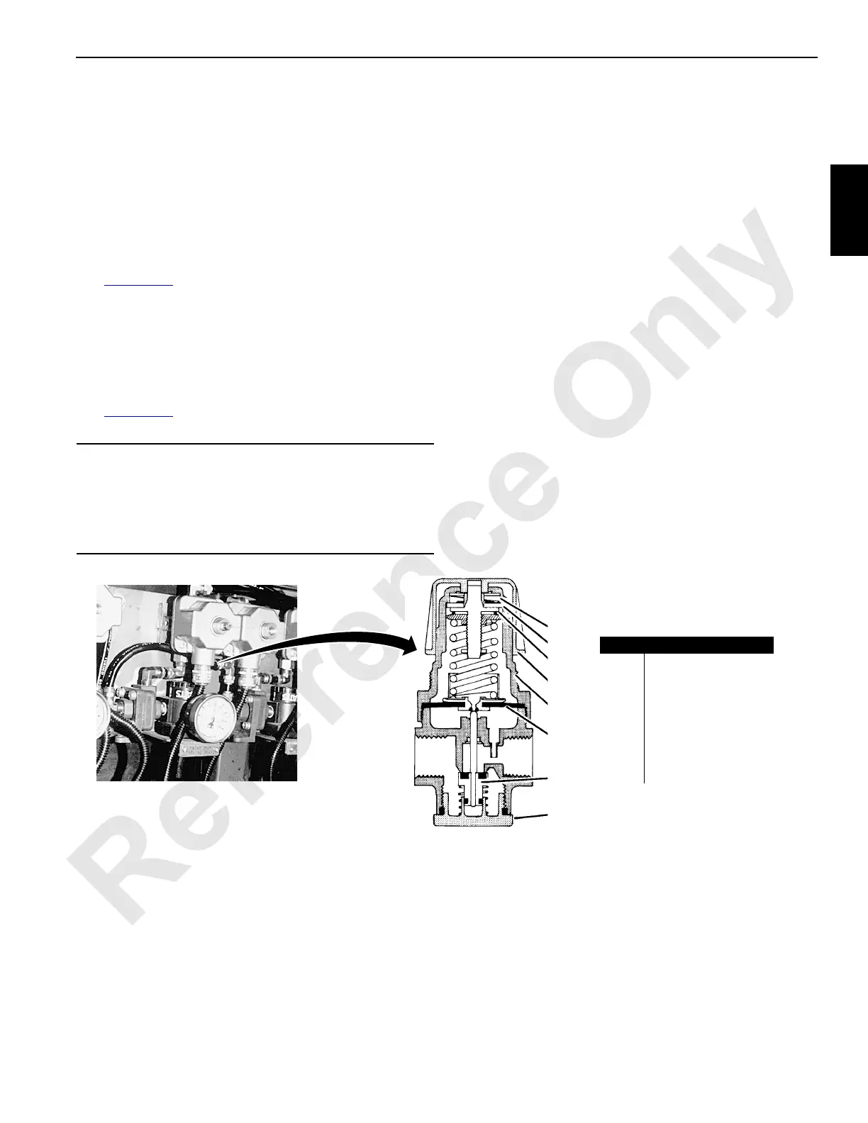
FIGURE 2-43
Item Description
1 Lock Assembly
2 Adjustment Screw
3 Adjustment Knob
4Knob
5 Spring Cage
6 Diaphragm Assembly
7 Disc Assembly
8 Bonnet
1
2
3
4
5
6
7
8

 Loading...


