Manitowoc Published 07-19-16, Control # 249-01 2-9
2250 SERVICE/MAINTENANCE MANUAL HYDRAULIC AND AIR SYSTEMS
Table 2-8. Split Flange Leakage
SAE Flare Connection
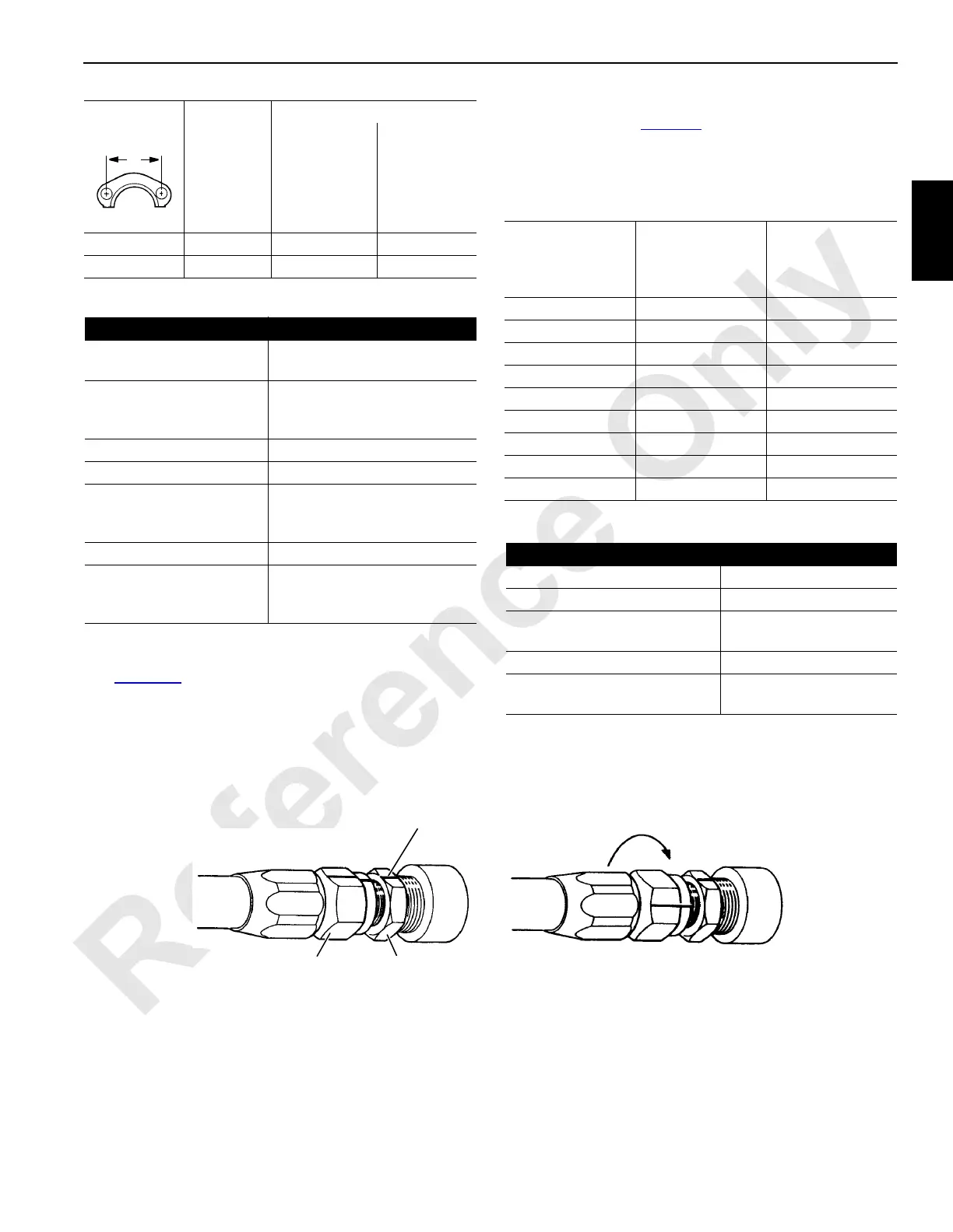
See Figure 2-9 for the following procedure.
1. Tighten the nut finger tight until the sealing surfaces
touch.
2. Using a felt pen or marker, mark a line on the adapter
and extend it onto the connector nut (View A).
3. Using wrenches, tighten the connector nut the number
of flats shown in Table 2-9
.
Misalignment of the marks will show how much the nut
has been tightened.
Table 2-9. SAE 37° Flare Tightening
Table 2-10. SAE 37° Flare Leakage
3-1/8 -24 158 to 181 1400 to 1600
3-13/16 -32 271 to 294 2400 to 2600
Cause Cure
Flanges not tight Tighten bolts evenly to proper
torque
Flanges tightened
unevenly causing
extrusion of O-ring
Replace O-rings and tighten
bolts evenly to proper torque
O-ring cut Replace
O-ring wrong size Replace with proper size
Sealing surfaces are not
smooth. They are
scratched or gouged.
Repair if possible or replace
parts
Sealing surfaces dirty Clean
Flanges keep getting
loose in service
Use SAE grade 5 bolts or
better and retighten bolts after
system is hot
Dimension A
inch
Flange
Size
Torque
Nm in-lb
Connector Nut
Size
(inch across
flats)
Fitting Size
Adapter Flats
to Rotate
9/16 -04 2-1/2
5/8 -05 2-1/2
11/16 -06 2
7/8 -08 2
1 -10 1-1/2 to 2
1-1/4 -12 1
1-1/2 -16 3/4 to 1
2 -20 3/4 to 1
2-1/4 -24 1/2 to 3/4
Cause Cure
Joint loose Tighten properly
Sealing surfaces dirty Clean
Sealing surfaces are scratched
or gouged
Replace faulty parts
Sealing surfaces cracked Replace faulty parts
SAE 45° parts used with SAE
37° parts
Use only SAE 37°parts
S108
FIGURE 2-9
Connector
Nut
Adapter
Line
Turn connector nut required number of flats
View A View B
 Loading...


