HOISTS 2250 SERVICE/MAINTENANCE MANUAL
5-12
Published 07-19-16, Control # 249-01
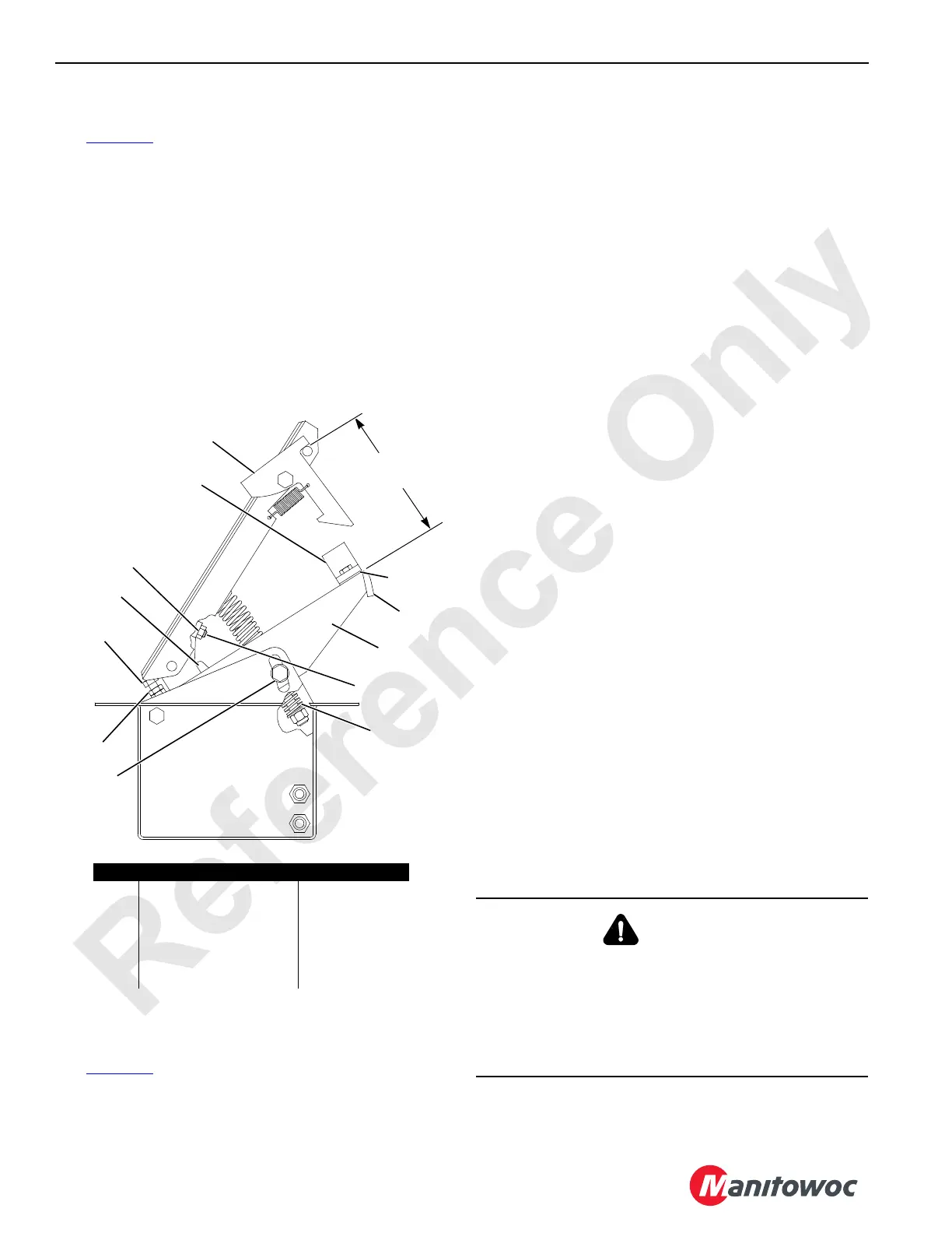
Checking the Treadle Valve
See Figure 5-9 for the following procedure.
1. Check the pedal latch (11) and latch bar (12) for wear.
The pedal latch must hold the pedal down in the fully
applied position.
2. Connect a 0 to 10,3 bar (0 to150 psi) air pressure gauge
to the In and Out ports of the valve (6) and observe the
following:
• Air pressure at the In port should be 8,3 to 9,1 bar
(120 to 132 psi).
• Air pressure at the Out port should modulate from 0
to 5,2 bar (0 to 75 psi) as the pedal is slowly
depressed and then go to 8,3 to 9,1 bar (120 to
132 psi).
Adjusting the Treadle Valve
See Figure 5-9 for the following procedure.
1. Lower the load for the treadle valve being adjusted to the
ground so the load line is slack.
2. Adjust the pedal to the desired height as follows.
a. Latch the pedal down.
b. Loosen the four capscrews (1).
c. Move the valve support (2) to the desired height.
d. Securely tighten the capscrews.
3. Adjust the spring (3) for a 73 mm (2-7/8 in) preload.
4. Install shims (4) under the bumper (5) so the pedal
compresses the bumper 0,8 mm (1/32 in) when the
pedal is latched.
5. Adjust the valve (6) as follows.
a. Release the brake pedal to the fully raised position.
b. Connect a 0 to 10,3 bar (0 to 150 psi) air pressure
gauge to the Out port between the valve and the
actuator.
c. Depress the pedal so it is approximately 0,8 mm (1/
32 in) from touching the bumper. The gauge should
read 7,9 to 8,6 bar (115 to 125 psi).
Do not set the pressure higher than 8,6 bar
(125 psi).
d. If required, loosen the jam nut (7) and tighten the set
screw (8) to increase the pressure. Loosen the set
screw to decrease the pressure. Securely tighten
the jam nut to lock the adjustment.
e. Release the brake pedal to the fully raised position.
The gauge should read 0 bar (0 psi). If required,
loosen the jam nut (9) and turn the screw (10) in
until the pressure is 0 bar (0 psi). Securely tighten
the jam nut to lock the adjustment.
f. Remove the gauge.
g. Repair or replace the valve if the correct pressures
cannot be obtained.
Overhauling the Brake Actuator
FIGURE 5-9
5-1/4 in
(133 mm)
In
Out
B225
Item Description Item Description
1 Capscrew (qty 4) 7 Jam Nut
2 Valve Support 8 Set Screw
3Spring 9Jam Nut
4 Shim (qty varies) 10 Screw
5 Bumper 11 Pedal Latch
6 Valve 12 Latch Bar
1
2
3
4
5
6
7
8
9
10
11
12
WARNING
Personal Injury Hazard!
The actuator is spring-loaded and will fly apart with
dangerous force if not disassembled correctly.
Do not attempt to disassemble the actuator while it is on
the crane. See the instructions in the manufacturer’s
service manual for proper disassembly of the actuator.

 Loading...


