BOOM 2250 SERVICE/MAINTENANCE MANUAL
4-8
Published 07-19-16, Control # 249-01
Raising the Boom Stop to the Working
Position
See Figure 4-4 for the following procedure.
1. Connect the socket to the plug in the air supply line near
the right side boom hinge pin as shown in View C.
2. Start the engine. The strut cylinders will extend to raise
the boom stop tubes as air pressure is supplied.
3. Remove the quick-release pin from both strut supports
and rotate the supports to the working position as
shown.
4. Reinstall the quick-release pins to lock the struts in
position.
Adjustments
See Figure 4-4 for the following procedures.
The physical boom stop was adjusted at the factory and
does not require periodic adjustment. The following items
must be verified and adjusted at assembly, however, if the
boom stop is disassembled for repair or parts replacement.
Boom Stop Rod Ends
Verify that each boom stop rod end is threaded all the way
onto the cylinder rod so the rod end is snug against the
shoulder on the cylinder rod as shown in View B. Also, make
sure to install the rod end guides. The guides keep the boom
stop rod ends in proper alignment.
Boom Stop Engagement
Watch the boom stop rod ends while slowly raising the boom
butt. Both of the rod ends must engage the boom stop pins in
the rotating bed at the same time and at the approximate
point shown in View B. Adjust the boom stop rod end for
each strut cylinder to provide the proper engagement.
Boom Stop Compression
Watch the boom stop rod ends while slowly raising the boom
butt. With the boom butt at 90
°, both boom stop rod ends
should be bottomed out against the cylinders to within
3,2 mm (1/8 in) of each other as shown in View D.
Install the U-shaped spacers between the cylinder flanges
and the boom stop tubes as shown in View D to limit the
maximum angle to 90
° and to bottom out the rod ends to
within 3,2 mm (1/8 in) of each other.
ANGLE INDICATOR SENDING UNIT
ASSEMBLY
General
See Figure 4-6 for the following.
An angle indicator sending unit (2) is mounted on the boom
butt (6) and, if equipped, on the luffing jib butt (1).
Each sending unit houses an angle sensor that sends an
electrical signal to the crane’s programmable controller. The
programmable controller converts the signal into an angle
which can be monitored on the digital display in the
operator’s cab.
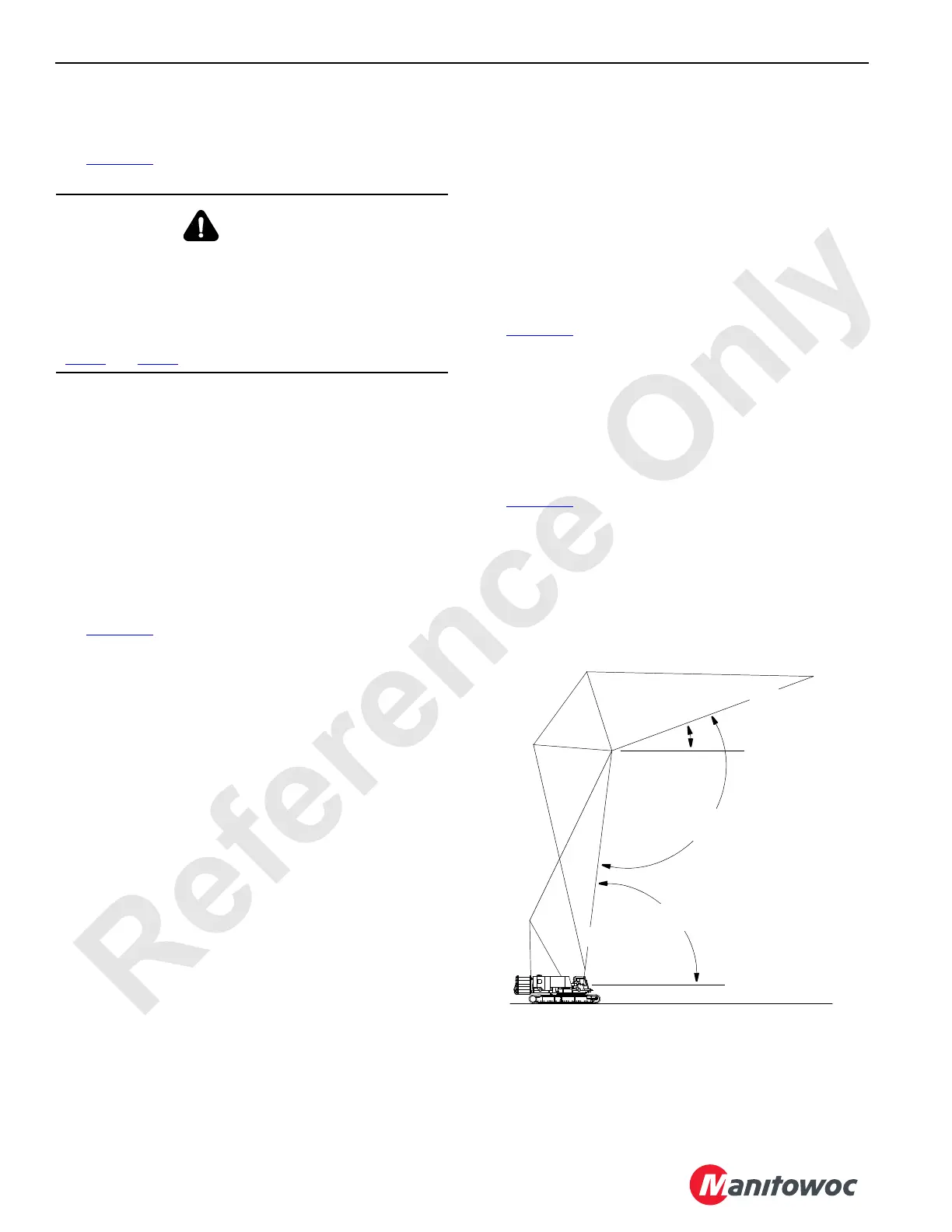
See Figure 4-5
for the following.
The following three angles can be monitored:
• Boom angle
• Luffing jib angle
• Boom-to-luffing jib angle
WARNING
Crushing Injury Hazard!
The strut cylinders will extend as air pressure is supplied,
creating a hazardous situation in which death or serious
injury may occur.
Stand clear of the boom stop tubes while performing
step 1
and step 2.
Boom and Jib Angle Identification
A528
C
L
C
L
Boom
Boom-to-Luffing
Jib Angle
Boom Angle
Horizontal
Horizontal
Luffing Jib
Luffing Jib
Angle
FIGURE 4-5

 Loading...


