Manitowoc Published 07-19-16, Control # 249-01 7-11
2250 SERVICE/MAINTENANCE MANUAL POWER TRAIN
ENGINE THROTTLE ADJUSTMENT
The throttle assembly consists of an electronic control
module (ECM) on the engine, a hand throttle controller in the
left console, a foot pedal (10) and a foot throttle
controller (15) on the cab floor (14), associated linkage, and
electrical connections.
A reach rod (4) connects the foot pedal to the lever
assembly (12) on the foot throttle controller. An electric cable
connects the hand throttle controller in the left control
console to the foot throttle controller.
Engine high idle and low idle speed is calibrated
automatically by the crane’s programmable controller.
Foot Throttle Linkage Adjustment
See Figure 7-10 for the following procedure.
1. Install the spring clip (1) and rod end (2) on the controller
lever assembly at the dimension shown in View A, and
securely tighten the jam nut (3).
2. Insert a 5 mm (3/16 in) thick shim or piece of floor mat
between the foot pedal and cab floor.
3. Press the foot pedal down fully to the high idle position
against the shim or floor mat.
4. Loosen the jam nuts (6). Adjust the reach rod and rod
end (5) so the controller lever is rotated fully to the high
idle position. Securely tighten the jam nuts (6) to lock the
adjustment.
NOTE: The controller has internal stops at the high and
low idle positions.
5. Release the foot pedal to the low idle position.
6. Adjust the return spring (16) so there is sufficient force to
raise the foot pedal and rotate the controller lever to the
low idle position.
7. Loosen the jam nut (8). Adjust the pedal stop screw (7).
The screw must be tight against the cab floor, and there
must be a 31 mm (1/8 in) gap between the pin (9) and
the rear end of the slot in the rod end. Securely tighten
the jam nut (8).
8. With the foot pedal in the low idle position, the distance
from the top of the foot pedal to the cab floor should be
100 mm (3-15/16 in).
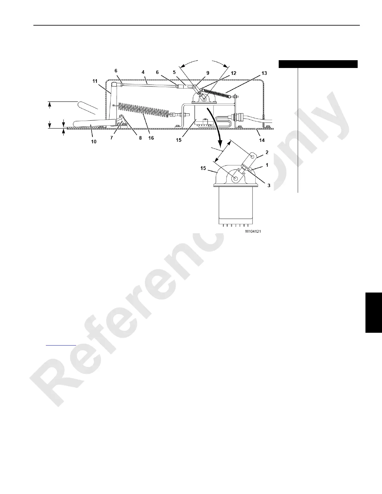
FIGURE 7-10
Item Description
1 Spring Clip
2 Rod End
3Jam Nut
4 Reach Rod
5 Rod End
6Jam Nut (qty 2)
7 Pedal Stop Screw
8Jam Nut
9Pin
10 Foot Pedal
11 Foot Pedal Lever
12 Lever Assembly
13 Spring
14 Cab Floor
15 Foot Throttle Controller
16 Return Spring
100 mm
(3-15/16 in)
5mm
(3/16 in)
75°
Ref.
57 mm
(2-1/4 in)
Low Idle
High Idle
Low Idle
High Idle

 Loading...


