Manitowoc Published 07-19-16, Control # 249-01 3-7
2250 SERVICE/MAINTENANCE MANUAL ELECTRICAL SYSTEM
TEST VOLTAGES FOR CRANE
CONTROLLER
General
This section contains test voltages sorted into the following
four categories:
• Pin identification
• Wire identification
• Description identification
• Master node pin identification
NOTE: The master node is only present on CraneSTAR-
equipped machines.
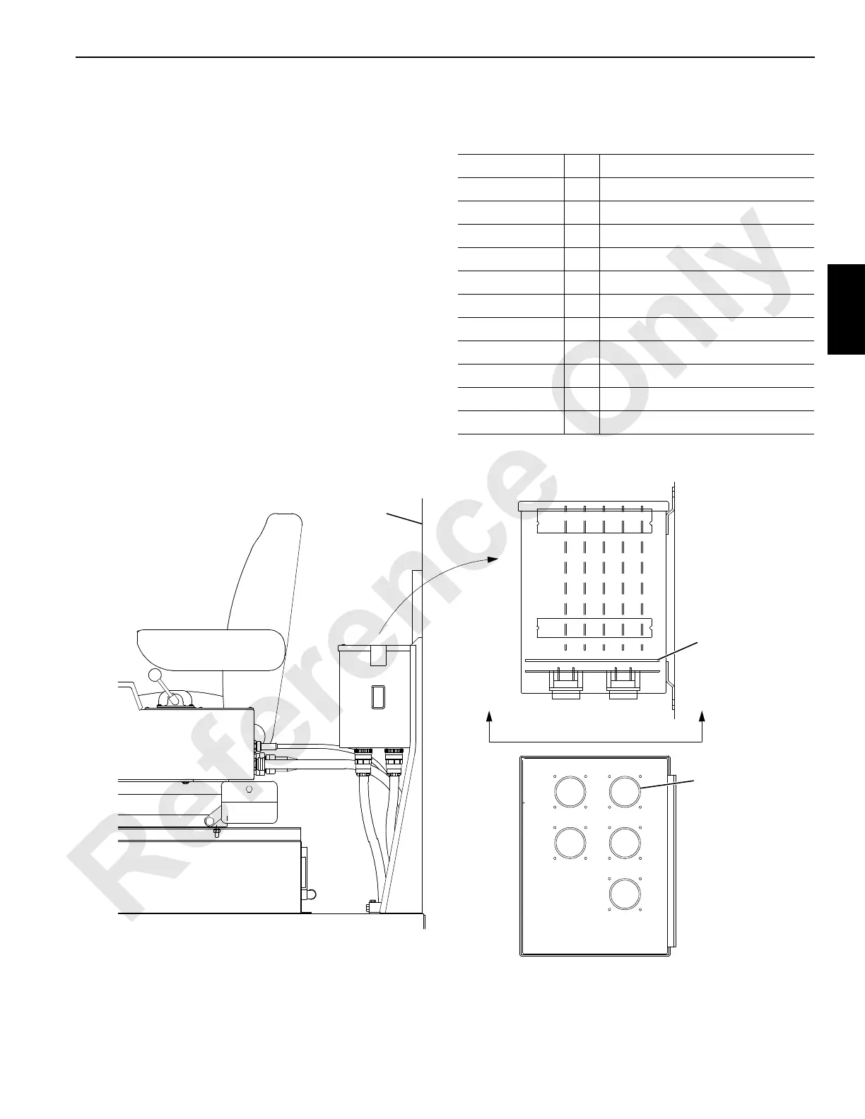
Controller Board Layout
The board locations in the cab programmable controller are
shown below. The MAX-ER programmable controller is
located in an electrical junction box behind the operator’s
cab (on the left side of the rotating bed).
Abbreviations
The following abbreviations are used in this section:
AI = Analog Input
AO = Analog Output
CHA or CHB = Channel A or B
Comm = Communication
CPU = Central Processing Unit
DI = Digital Input
DO = Digital Output
I/O = Input/Output
lb = Pounds
N/C = No Connection
Press = Pressure
psi = Pounds per Square Inch
E
D
B
C
A
CPU BOARD
I/O BOARD 1
I/O BOARD 2
I/O BOARD 3
I/O BOARD 4
Rear Cab
Wall
Mother
Board
Cable
Connector
A1105
FIGURE 3-6

 Loading...


