Manitowoc Published 07-19-16, Control # 249-01 5-23
2250 SERVICE/MAINTENANCE MANUAL HOISTS
c. If necessary, loosen the mounting screws and
reposition the band guide to obtain the specified
clearance. Securely tighten the mounting screws.
13. Reinstall the cover over the access hole.
Band Disassembly and Assembly Notes
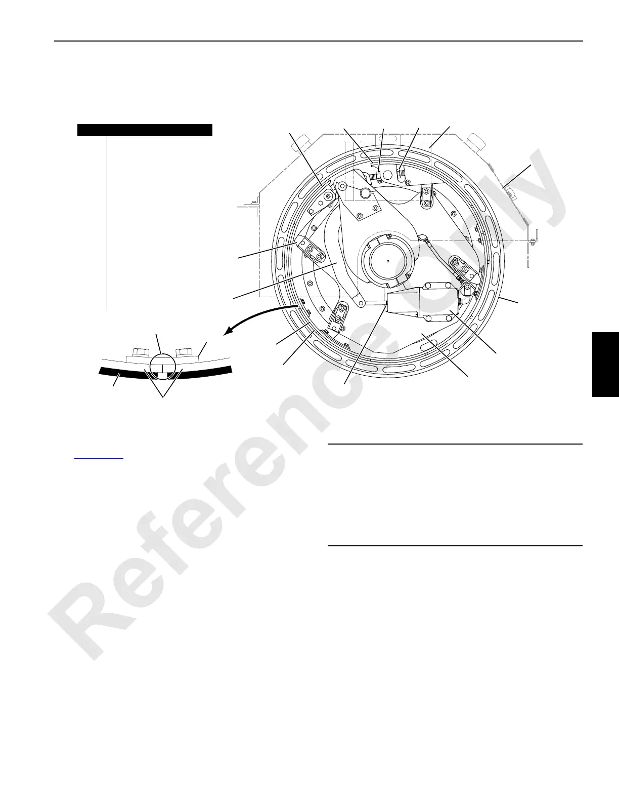
See Figure 5-17 for the following.
Each clutch band consists of three segments fastened
together with a connecting plate (14) and capscrews (see
View A).
When reassembling a clutch band, match the numbers
stamped on each end of the band sections (15) with the
number stamped on the connecting plates.
FIGURE 5-17
2
22
Mark A
Matching
Numbers
View A
A1147
Item Description
1 Dead End
2Live End
3 Adjusting Nut
4Jam Nut
5 Access Hole
6 Guard
7 Drum Flange
8 Air Cylinder
9 Clutch Spider
10 Lining
11 Clutch Band
12 Clutch Lever
13 Band Guide (qty 4)
14 Connecting Plate
15 Band Section (qty 2)
1
2
3
4
5
6
7
8
9
10
11
12
13
14
15
10
CAUTION
Component Assembly!
Band segments from different drums may make assembly
difficult and cause equipment damage.
Do not mix band segments from one drum with those from
another drum. Always keep band segments in a matched
set.
 Loading...


