Manitowoc Published 07-19-16, Control # 249-01 1-87
2250 SERVICE/MAINTENANCE MANUAL INTRODUCTION
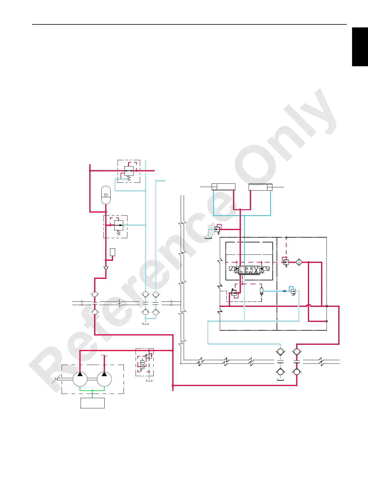
Steering Cylinders Retract (Straight)
The steering pins must be disengaged first, before the
steering arms can be positioned. Move the stop pins to the
desired steering position. When the steering switch is held in
the DOWN (straight) position, an input signal is sent to the
PC. A 12 V output signal from the PC enables the steering
solenoid valve HS-43 to retract the right side and left side
steering arm cylinders. Internal pilot supply pressure of
14 bar (200 psi) enables the selected spool to shift the
steering arm retract solenoid valve.
The crane’s PC sends an output signal to shift the crane’s
auxiliary system disable-relief valve HS-12 to block the
valve’s bypass. Accessory system pressure increases to
operate the accessory items. An inline relief valve set at
183 bar (200 psi) reduces the auxiliary system’s pressure to
the steering arm cylinders.
Accessory system fluid enters the MAX-ER’s accessory
valve and goes through the steering solenoid valve to the rod
end of the steering cylinders to retract the steering cylinders
and move the steering arms to the straight position. Return
fluid from the piston end of the cylinders passes through the
MAX-ER’s accessory valve before returning to the crane’s
hydraulic tank through the return line. Release the steering
switch to stop retracting the steering arms when the stop is
reached. When the steering arms are positioned, the
steering pins must be engaged.
Extend Retract
Right Steering
Cylinder
Left Steering
Cylinder
(1,200 psi)
C2C1
138 bar
Wheeled Counterweight Trailer
X
(200 psi)
13,8 bar
XX
X
RM-12
HS42
HS43
MAX-ER Accessory Valve
FIGURE 1-56
152 bar
Stop Cylinders
From Mast
Stop Cylinders
To Mast
Mast
Accumulator
T
To Jib Strut
Cylinders
Jib Strut
Cylinders
From
Pressure
Sender
Accumulator
Mast
207 bar (3,000 psi)
(2,200 psi)
83 bar
207 bar
(3,000 psi)
(2,000 psi)
Accessory
To Crane
Crane
Manifold
Suction
Aux
Fan
Valves
HS12
Valve
Disable-Relie
f
Auxiliary System
 Loading...


