HOISTS 2250 SERVICE/MAINTENANCE MANUAL
5-24
Published 07-19-16, Control # 249-01
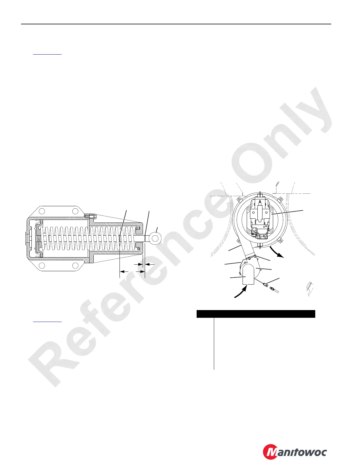
Marking the Cylinder Rod
See Figure 5-18 for the following procedure.
If a new cylinder is installed, it must be marked before
installation to ensure proper clutch adjustment. A 6,9 bar
(100 psi) shop air supply is required.
1. With the cylinder fully retracted, place a temporary mark
on the cylinder rod flush with the cylinder body. Use a
marker. Do not use a file or hacksaw blade.
When the rod retracts, the distance from the cylinder end
to the cylinder rod hole center is 27 mm (1-1/16 in).
2. Apply air to extend the cylinder so the temporary mark is
10 mm (3/8 in) from the end of the cylinder.
3. Mark the cylinder rod 6 mm (1/4 in) from the end of the
cylinder with a file or hacksaw blade (see Mark B).
4. Apply air to fully extend the cylinder rod. Make a second
mark on the cylinder rod 76 mm (3 in) down from Mark B
(see Mark A).
5. Remove the temporary mark.
GEARBOX COOLING BLOWER
See Figure 5-19 for the following procedure.
1. Remove the blower assemblies and thoroughly clean
them at the following intervals:
- Every 200 hours of operation in a humid climate
when operating in extremely dusty conditions
- Every 500 hours of operation under normal
operating conditions
2. Disconnect the electrical plug (1) from the plug on the
crane.
3. Support the blower (2) so it cannot fall and remove the
bolts with nuts and lock washers (3).
4. Remove the blower, guard (4), and inlet elbow (5).
5. Thoroughly clean the inside of the blower using a
compressed air jet. Use a putty knife to loosen material
as required.
6. Make sure the squirrel cage turns freely.
7. Thoroughly clean the inlet elbow.
8. Make sure the exhaust hole in the shroud (6) is open.
9. Reassemble the guard and blower to the shroud.
10. Clamp the inlet elbow to the blower so the elbow points
down.
11. Connect the electrical plug to the plug on the crane.
12. Start the engine and test the blower for proper operation.
Air should flow freely from the exhaust hole.
FIGURE 5-18
6 mm
(1/4 in)
Mark A
76 mm
(3 in)
Cylinder
Rod
Mark B
A1114
A1202
Air
Exhaust
Air Inlet
1
2
3
4
5
6
7
Item Description
1Electrical Plug
2Blower
3 Bolts with Nut and Lock Washer (qty 4)
4 Guard
5 Inlet Elbow
6 Shroud
7 Drum Motor
FIGURE 5-19
 Loading...


