Manitowoc Published 07-19-16, Control # 249-01 2-25
2250 SERVICE/MAINTENANCE MANUAL HYDRAULIC AND AIR SYSTEMS
UNLOADER PILOT VALVE MAINTENANCE
General
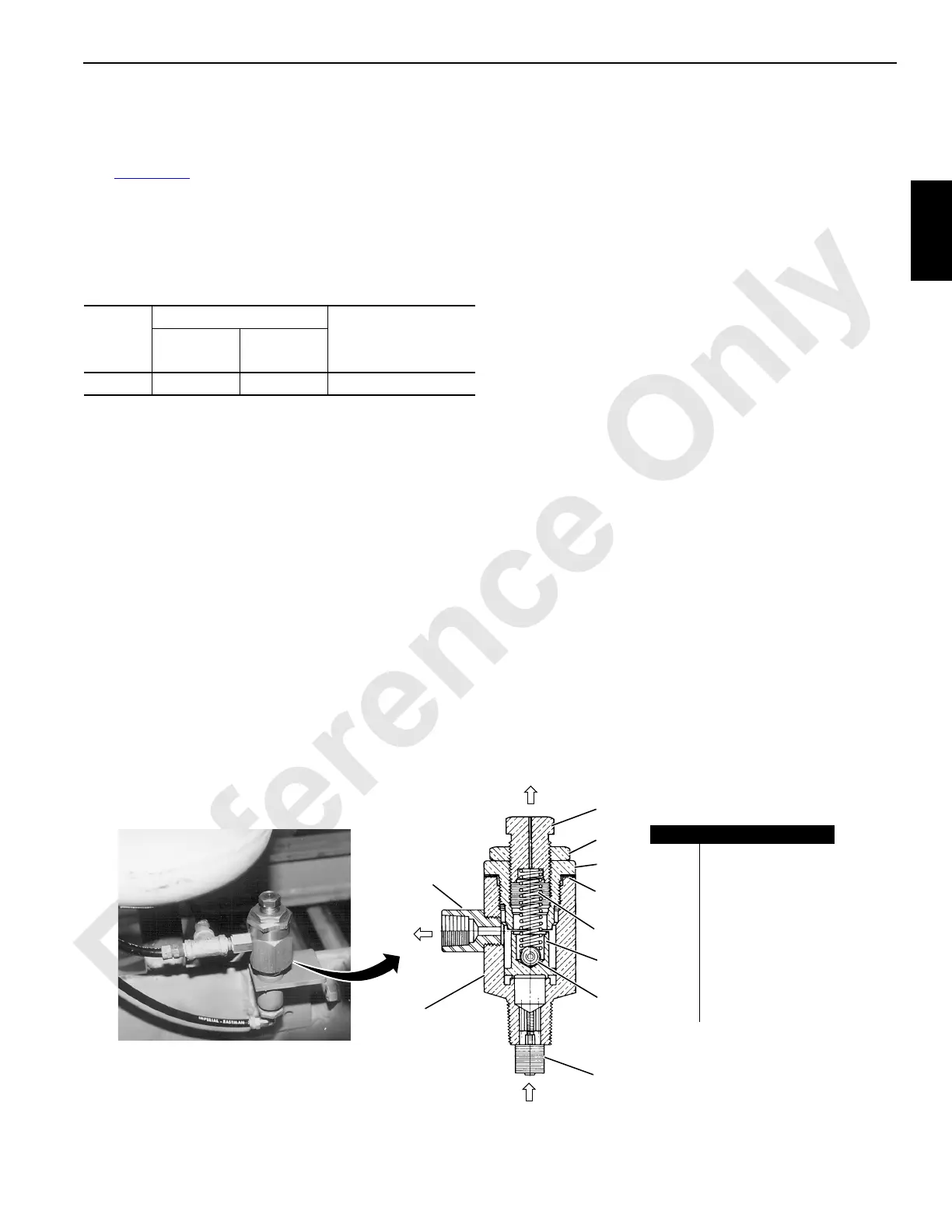
See Figure 2-28 for the following.
The unloader pilot valve automatically controls air system
pressure by controlling when the compressor starts and
stops compressing air.
Table 2-13. Unloader Pilot Valve Air System Pressure
Settings
Air pressure from the air tank acts against the unloader valve
(8) during operation.
As air system pressure increases, the unloader valve moves
up against the resistance of the unloader spring (6). When
the air pressure reaches the cut-out setting, the unloader
valve seats against the unloader cap (4). This action closes
the exhaust port in the adjusting screw (2) and opens a flow
path from the air tank to the compressor unloading
mechanism. The air compressor then stops compressing air.
When air system pressure decreases to the cut-in setting,
the unloader spring (6) forces the unloader valve (8) down,
seating it against the unloader body (7). This action closes
the flow path from the air tank and opens the exhaust port in
the adjusting screw (2). The air at the compressor unloading
mechanism then exhausts, and the compressor starts
compressing air.
Adjustment
The unloader pilot valve has a 0,83 bar (12 psi) range
between the cut-out and cut-in pressures. The range is fixed
and can be changed only slightly by removing or installing
shims (5). Remove one shim to increase the range or add
one shim to decrease the range.
To adjust the cut-out setting, loosen the lock nut (3) and turn
the adjusting screw (2) in to increase the pressure or out to
decrease the pressure. Hold the adjusting screw and
securely tighten the lock nut.
Maintenance
If the unloader pilot valve sticks or flutters, take it apart and
clean it thoroughly in nonflammable solvent. Be sure to clean
the filter (10) by removing it and washing it thoroughly in a
nonflammable solvent. Be sure to reinstall the filter, since it is
important that no foreign matter enters the valve chamber.
In case of unsatisfactory operation, perform the following
services.
1. Check the compressor unloading mechanism for
damage (see the air compressor manufacturer’s
manual).
2. Disconnect the air line from the air tank at the unloader
pilot valve, and blow out all oil, sludge, and scale.
3. Disassemble the entire unloader pilot valve. Wash all
parts in a nonflammable solvent and reassemble.
4. In case of major repair work, return the unloader pilot
valve to the valve manufacturer. The manufacturer has
the special tools and testing equipment required to lap
and align the seating surfaces.
Model
Unloader Pilot Valve
Safety Valve
Cut-In
1
bar (psi)
1
Cut-in is the pressure at which the air compressor
starts compressing air.
Cut-Out
2
bar (psi)
2
Cut-out is the pressure at which the air compressor
stops compressing air.
2250 8,3 (120) 9,1 (132) 11,4 bar (165 psi)
Item Description
1 Unloader Outlet
2 Adjusting Screw
3 Lock Nut
4 Unloader Cap
5 Unloader Cap Shim
6 Unloader Spring
7 Unloader Body
8 Unloader Valve
9Valve Ball
10 Filter
P296
S109
FIGURE 2-28
Unloader Pilot Valve
Typical Mounting Near
Air Tanks for Compressor
From Air
Tank
To A i r
Compressor
Exhaust
1
2
3
4
5
6
7
8
9
10
 Loading...


