Manitowoc Published 07-19-16, Control # 249-01 1-33
2250 SERVICE/MAINTENANCE MANUAL INTRODUCTION
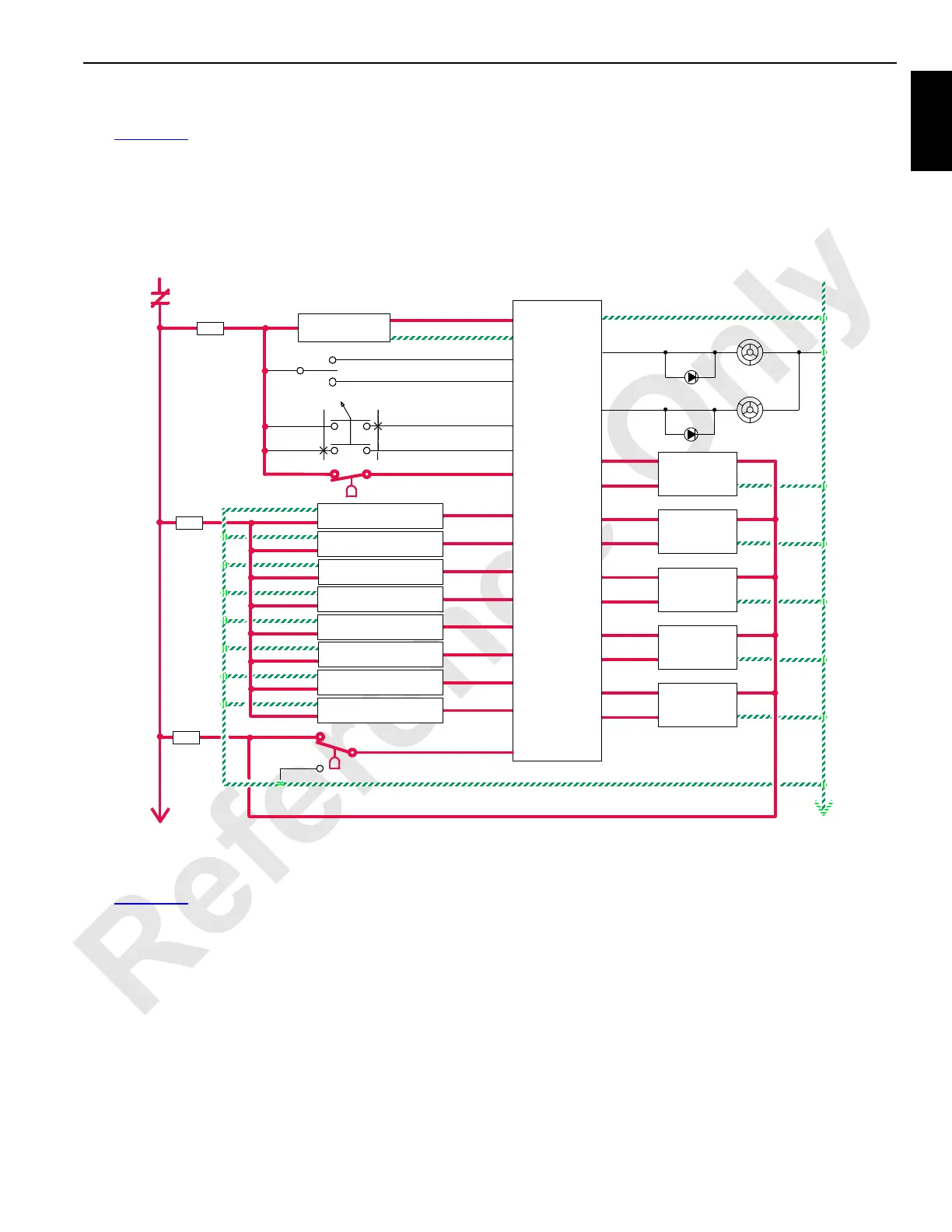
Pressure Senders and Speed Sensors
See Figure 1-17 for the following.
The pressure senders monitor the drum system pressures,
load drum charge pressure, right/left travel system pressure,
and swing right/left system pressure. The PC receives input
hydraulic pressure information from each of the system’s
pressure senders. The pressure senders provide information
for the required load-holding pressures for the load drums,
boom hoist drum, or luffing hoist drum.
The drum speed sensors on the drum shafts or flanges
detect speed and direction of the drum’s movement. The PC
receives this information as two out-of-phase square wave
voltages that are converted to “counts.” The PC compares
the control handle’s voltage with the pump’s output to
determine when to vary the pump’s stroke.
Limit Switches and Faults
See Figure 1-18 for the following.
When operating, all of the limit switches are closed, sending
an input voltage to the PC. If a limit switch is tripped, the PC
sends a 0 V output to the system pump’s EDC and the brake
solenoid. The system’s pump de-strokes, and the system’s
brake solenoid valve shifts to apply the brake. Adjust the
component that tripped the limit switch in the opposite
direction from the limit switch to correct the problem.
The limit-bypass switch allows the crane to be operated
beyond the limits for crane setup or maintenance only, such
as adding or removing wire rope from the load drum after an
operating limit is enabled. The jib up limit-bypass switch
allows the jib maximum up limit to be bypassed when the
boom or luffing jib is lowered to the ground.
Hydraulic Brake Systems
Travel, swing, boom hoist, and luffing jib hoist brakes are
spring set and hydraulically released. The operator enables
brake operation by placing the selected brake switch in the
OFF position. The PC releases the swing brake immediately
when the swing brake switch is placed in the OFF position.
The PC controls the release of the other brakes with the
control handle’s movement.
Low Air Switch
WB-20
WD-20
WD-19
8D8
WD-11
WB-24
Select
Confirm
Crane Mode
8T
8
0
5A
0
8
WB-26
WB-33Down Scroll
Up Scroll
WA-26
WA-28
WA-23
WA-27
WA-24
WA-22
WA-19
WA-25
K1
RF-10
F10
WE-02
WE-01
8E
0
Front
(drum 1)
Speed
Sender
F
A
B
D
F12
Pressure Sender
Swing Left
Pressure Sender
Swing Right
Pressure Sender
Left Travel
Pressure Sender
Right Travel
Pressure Sender
Boom Hoist
Pressure Sender
Load Drum System
Pressure Sender
Load Drum Charge
Pressure Sender
Luffing Hoist or Accessory
8E
8
F11
System Fault
Alarm
WC-35
WC-34
Operating Limit
Light
Alarm
Light
WE-04
WE-03
8E
0
Right Rear
(drum 2)
Speed
Sender
F
A
B
D
WE-06
WE-05
8E
0
Left Rear
(drum 3)
Speed
Sender
F
A
B
D
WD-06
WD-05
8E
0
Boom Hoist
Speed
Sender
F
A
B
D
WD-02
WD-01
8E
0
Luffing Jib
Speed
Sender
F
A
B
D
D
(drum 4)
(drum 5)
Programmable
Controller
Hydraulic Vacuum Switch
WA-31
Digital Display
5A
5A
5A
FIGURE 1-17

 Loading...


