TROUBLESHOOTING 2250 SERVICE/MAINTENANCE MANUAL
10-40
Published 07-19-16, Control # 249-01
Test 7—Testing for Pump and Motor Leakage
Testing for pump and motor leakage requires a 207 bar
(3,000 psi) in-line flow meter (2) with a minimum flow rate
capacity of 113 L/min (30 gpm). Flow meters can be ordered
from Manitowoc Cranes.
Acceptable leakage is based on the combined case flow of
the pump and motor. The combined case flow of the load
drum pump and motor should be equal to a charge pump
flow or 34 L/min (8.9 gpm) per 1,000 rpm of the engine.
The combined case flow of the boom hoist, swing, travel, or
luffing jib hoist pump and motor should be equal to a charge
pump flow or 18 L/min (4.8 gpm) per 1,000 rpm of the
engine. The difference between the system charge pump
flow and motor case flow at neutral is the acceptable pump
case flow at neutral for the system being tested.
Motor Test
The external loop flush valve must be removed from the
boom hoist motor before testing (see Test 22—Servicing the
Motor Loop Flushing (Purge) Valves). To test a motor,
perform the following.
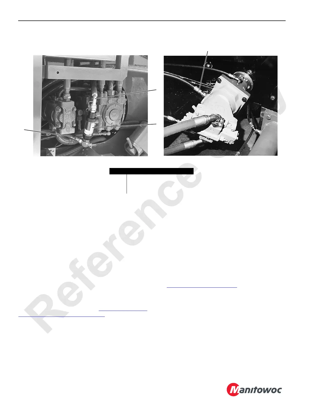
1. Connect the flow meter between the motor case drain
hose (1) and the highest motor case drain port.
2. With the engine running at 1,000 rpm, measure the flow
rate of the motor.
The case flow at neutral or very light loads should be
approximately 19 L/min (5 gpm).
3. Record all measurements at neutral.
At heavier loads, the normal case flow may go to 26 L/
min (7 gpm).
For motors that do not have loop flushing, the case flow
at neutral should not exceed 6 L/min (1.5 gpm).
For motors that do not have loop flushing, the case flow
at heavier loads and higher rpm may increase to 17 or
21 L/min (4.5 or 5.5 gpm).
4. Reconnect the motor case drain hose to the motor drain
port.
Pump Test
See Test 8—Location of Pump Ports for the location of the
pump ports. To test a pump, perform the following.
1. Connect the flow meter between the pump case drain
hose and pump port L1 or L2.
Use the highest port for testing.
2. With the engine running at 1,000 rpm, measure the flow
rate of the pump at neutral and compare it to the
calculated acceptable pump case flow.
Deviations from the normal or major changes with increasing
system pressure more than +/-4 L/min (1 gpm) are an
indication of a pump or motor problem.
P1532
P894
Pumps
Motors
1
2
3
3
FIGURE 10-8
Item Description
1 Case Drain Hose
2 In-Line Flow Meter
3 Hose to Highest Case Drain Port
 Loading...


