Manitowoc Published 07-19-16, Control # 249-01 4-11
2250 SERVICE/MAINTENANCE MANUAL BOOM
Angle Indicator Sending Unit
The angle indicator sending unit is a solid state sensor
assembly. The sending units for the boom and the luffing jib
are identical in appearance. However, the two units function
differently and must not be interchanged.
The sending unit for the boom angle has a 120
° sensor. This
sensor is labeled 173010.
The sending unit for the luffing jib angle has a 180
° sensor.
This sensor is labeled 173732.
Replacing the Sensor
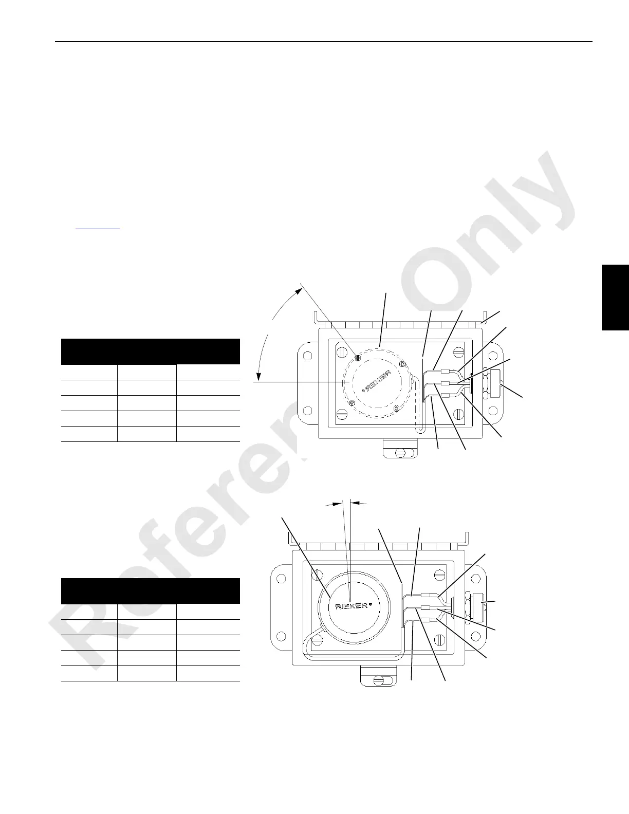
See Figure 4-8 for the following procedure.
To replace a sensor, perform the following.
1. Identify all input wires to the existing sensor.
2. Cut the existing input wires near the terminal strip (if
used) to allow for splicing.
3. Remove the existing sensor and the terminal strip (if
used).
4. Mount the new sensor in the existing holes at the angle
shown.
5. Refer to the wiring chart and parallel splice the sensor
wires to the existing input wires with crimp, solder, and
heat shrink tubing.
6. Seal the green wire on the sensor with heat shrink tubing
and coil up.
Solid State Sensor (+/- 60°)
M.C.C. #81033730
Vendor #CS53
Input Wires
Color
Sensor
Wires Color
Operation
Code
From To
Black Black Ground
Green White Signal
White Red 10 Volts DC
Green N/C
A1294
3-Pole
52.5° REF.
87FA - White
82BA - Green
0 - Black
Receptacle
Black
Green
Red
White
Position Sensor
Like This
Solid State Sensor (+/- 90°)
M.C.C. #81033734
Vendor #CS55
0 – Black
3-Pole Receptacle
with Protective Cap
82BA – Green
87FA – White
Black
Green
White
Red
Input Wire
Color
Sensor Wire
Color
Operation
Code
From To
Black Black Ground
Green White Signal
White Red 10 Volts DC
Green N/C
A1294
Position Sensor
Like This
3.2° REF.
FIGURE 4-8
 Loading...


