Manitowoc Published 07-19-16, Control # 249-01 10-57
2250 SERVICE/MAINTENANCE MANUAL TROUBLESHOOTING
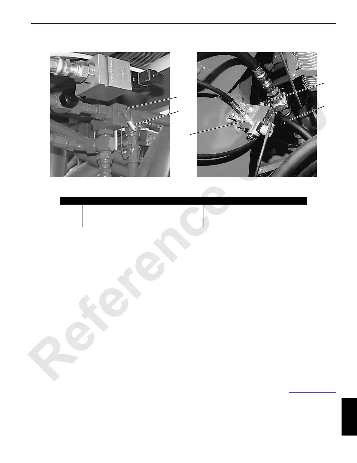
Test 23—Checking the Hydraulic Brake Pressure
The hydraulic brakes for the swing and travel systems
operate off the exhaust pressure from the fan motor system.
The boom/luffing jib brakes are released off the low-pressure
side or boom hoist closed-loop system. To check hydraulic
brake pressure for the swing and travel systems, perform the
following procedure.
1. Make sure the engine is off and the power is off, with all
brakes and locks engaged.
2. Connect a 0 to 69 bar (0 to 1,000 psi) gauge at the
diagnostic quick-disconnect fitting on the pilot/brake
pressure relief valve (1) between the top of the engine/
radiator and the oil cooler fans.
3. Start the engine and set it at high idle (2,000 rpm).
4. Enable the desired system brake and verify the brake
pressure is 22 to 26 bar (325 to 375 psi).
5. If the pressure is not within range, adjust the pilot/brake
pressure relief valve.
6. Loosen the adjusting lock nut.
7. Turn the adjusting screw clockwise (in) to increase
pressure until the correct pressure is obtained.
8. Turn the adjusting screw counterclockwise (out) to
decrease pressure until the correct pressure is obtained.
9. Secure the adjusting lock nut.
10. Remove the pressure gauge and replace the fitting cap.
11. If the correct pressure cannot be obtained, replace the
valve assembly.
To check the hydraulic brake pressure for the boom hoist
system, perform the following procedure.
1. Make sure the engine is off and the power is off, with all
brakes and locks engaged.
2. Connect a 0 to 69 bar (0 to 1,000 psi) gauge between
the 90° elbow (4) on the boom hoist brake control
valve (3) and the flexible hose (5).
3. Start the engine and set it at high idle (2,000 rpm).
4. Enable the boom hoist system brake and verify the
brake pressure is 22 to 26 bar (325 to 375 psi).
If equipped with a luffing jib, the system brake pressure
is 34 to 38 bar (500 to 550 psi).
5. If the pressure is not within range, check the boom/
luffing jib hoist charge pressure in Test 16—Checking
the Pump Charge Pressure and Electrical Test.
P970
P924
Swing and Travel Systems Boom/Luffing Jib System
1
2
3
4
5
FIGURE 10-26
Item Description Item Description
1 Pilot/Brake Pressure Relief Valve 4
90
° Elbow
2 Test Port (adjusting screw on opposite side) 5 Flexible Hose
3 Boom Hoist Brake Control Valve
 Loading...


