Manitowoc Published 07-19-16, Control # 249-01 2-43
2250 SERVICE/MAINTENANCE MANUAL HYDRAULIC AND AIR SYSTEMS
Decreasing Pressure
See Figure 2-47 for the following procedure.
As the brake pedal is eased up to release the drum brake,
reduced pressure at the pilot port unbalances the pressure
across the diaphragm assembly. This causes the diaphragm
assembly to move away from the seated inlet-valve plunger,
opening the OUT port to the exhaust passage. Air continues
to exhaust until the brake pedal is stopped or held at the
desired position. Pressure at the OUT port then becomes
equal to pressure at the pilot port (see Balanced Position on
page 2-42).
Maintenance
See Figure 2-48 for the following procedure.
The relay valve does not require periodic maintenance or
adjustment.
Overhaul the relay valve as follows if it fails to operate
properly.
NOTE: The relay valve can be overhauled without
disconnecting the air lines. All parts are accessible
by removing the cover.
1. Completely disassemble the relay valve. No special
tools are required.
2. Clean all metal parts with a nonflammable solvent. Wash
all rubber parts with soap and water.
3. Rinse all parts in clean water and blow dry them with a
low pressure air jet.
4. Lay all parts on a clean surface.
5. Examine each part for wear and cracks. Replace worn
parts. Parts contained in the repair kit for the relay valve
are identified in the exploded view.
6. Reassemble the relay valve.
7. During assembly, lubricate all metal-to-metal surfaces
with No. 107 Lubriplate and all rubber parts with
Cosmolube or their equivalent.
CAUTION
Flying Debris Hazard!
A sudden release of pressurized air can cause minor
injury due to flying debris.
Drain the air system before removing the relay valve
cover.
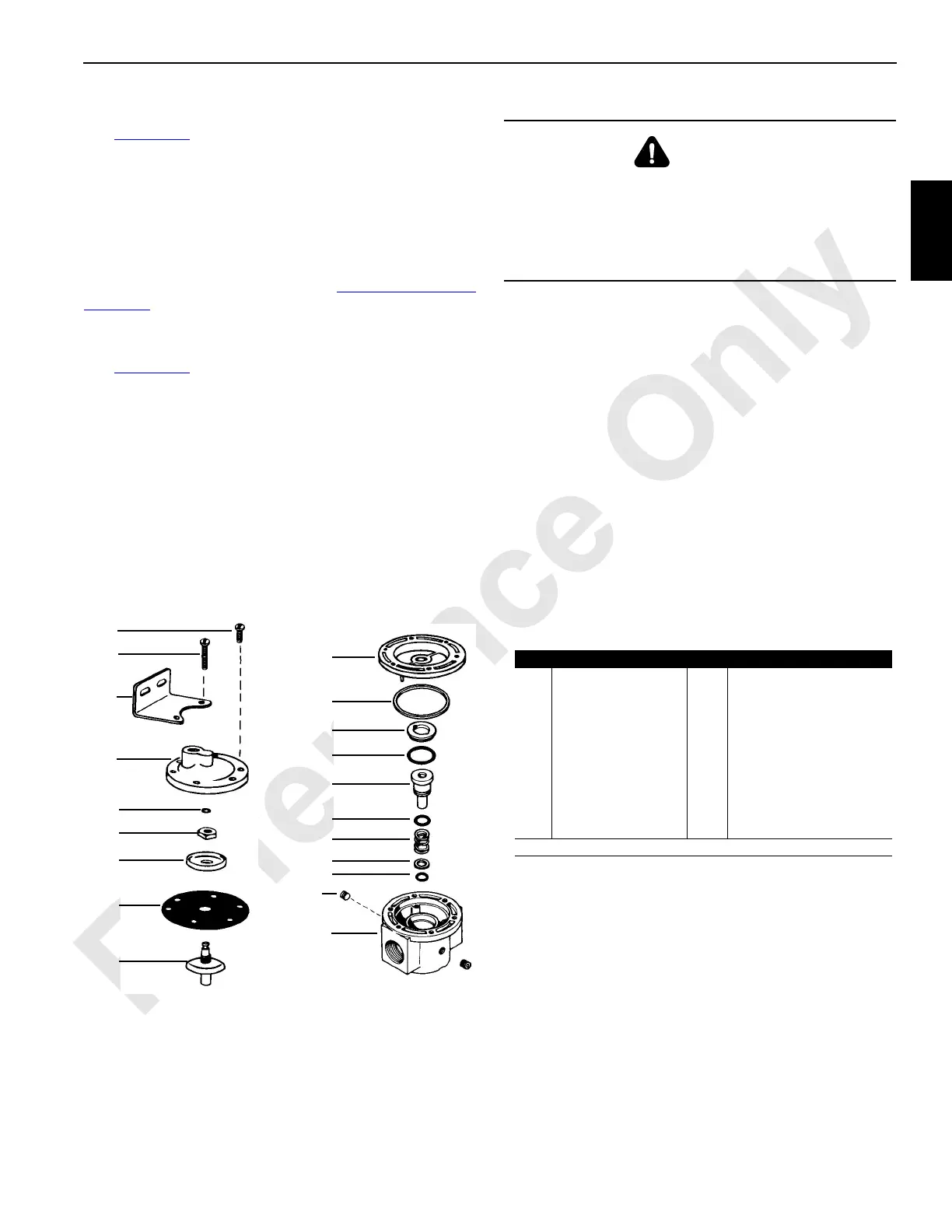
FIGURE 2-48
Relay Valve Assembly
Item Description Item Description
1 Body 11 Diaphragm Follower
2 O-ring* 12 Diaphragm*
3 Washer 13 Diaphragm Retainer
4 Inlet-Valve Spring* 14 Hex Nut
5 O-ring* 15 O-ring*
6 Inlet-Valve Plunger* 16 Cover
7 O-ring* 17 Screw (short) (qty 4 each)
8 Inlet-Valve Seat* 18 1/8 in Pipe Plug (qty 2 each)
9 O-ring* 19 Mounting Bracket
10 Baffle* 20 Screw (long) (qty 2 each)
*Parts in Repair Kit
S124
1
2
3
4
5
6
7
8
9
10
11
12
13
14
15
16
17
18
19
20
 Loading...


