INTRODUCTION 2250 SERVICE/MAINTENANCE MANUAL
1-28
Published 07-19-16, Control # 249-01
Pressurized Air Supply
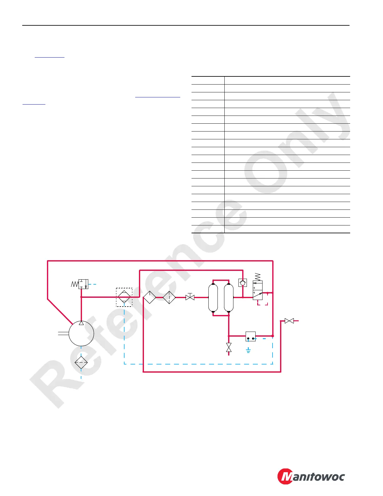
See Figure 1-13 for the following.
Pressurized air is provided to the crane's air cylinder
systems, such as the boom hoist pawl, luffing hoist pawl,
load drum pawls, load drum brakes, load drum clutches,
counterweight pin cylinders, backhitch pin cylinders, and
optional boom stop cushion cylinders. See Hydraulic and Air
Systems Section 2 for the Air Schematic drawing.
Airflow from the compressor passes through the air dryer
before entering the air tanks. An optional alcohol injector
provides de-icing, and condensation is eliminated through an
electrical moisture ejector.
The unloader valve adjusts the compressor delivery rate by
briefly opening the compressor's intake valve at 9 bar
(32 psi). The safety-relief valve limits pressure in the system
to 11,4 bar (165 psi). Another shut-off valve isolates air
supply from the air system.
Air tanks, filter, injector, ejector, and a shut-off valve are
mounted on the left side of the rotating bed. The unloader
valve and relief valves are located on the right side, near the
engine-mounted air compressor. The pressure sender
monitors air pressure and sends the information to the
programmable controller (PC). The digital display indicates
supply pressure. If the supply pressure drops to 6 bar
(90 psi), the PC enables an alert. The load drum brakes
apply automatically at 5,2 bar (75 psi).
Each air solenoid valve is assigned an AS number. The AS
number identifies each air solenoid valve.
Table 1-3. Air Solenoid (AS) Valves
AS-1 Backhitch Pins Extend
AS-2 Backhitch Pins Retract
AS-3 Lower Counterweight Pins Engage
AS-4 Lower Counterweight Pins Disengage
AS-5 Upper Counterweight Pins Engage
AS-6 Upper Counterweight Pins Disengage
AS-7 Front (drum 1) Brake
AS-8 Front (drum 1) Clutch
AS-9 Right Rear or Rear (drum 2) Brake
AS-10 Right Rear or Rear (drum 2) Clutch
AS-11 Right (drum 3) Brake
AS-12 Right (drum 3) Clutch
AS-13 Boom Hoist Pawl Out
AS-14 Boom Hoist Pawl In
AS-15 Luffing Jib Pawl Out
AS-16 Luffing Jib Pawl In
AS-17 Front (drum 1) Pawl Out
AS-18 Front (drum 1) Pawl In
AS-19 Rear (drum 2) Pawl Out
AS-20 Rear (drum 2) Pawl In
Air
Compressor
Moisture
Ejector
8M
Alcohol
Injector
Shut-off
Valve
Air
Filter
Unloader
Valve
(120 psi)
8.3 bar
Safety
Valve
(165 psi)
11,4 bar
Optional
Air Dryer
Air Reservoir
RF-06
0
37.4 CFM
Engine
Air
Cleaner
To Air System
Components
FIGURE 1-13
Drain
Valve
 Loading...


