HYDRAULIC AND AIR SYSTEMS 2250 SERVICE/MAINTENANCE MANUAL
2-24
Published 07-19-16, Control # 249-01
7. Extend the cylinders to raise the counterweights
approximately 0,3 m (1 ft) off the ground and stop.
8. Retract the cylinders to lower the counterweights to the
ground. Both cylinders should retract at the same speed.
If they do, go to step 9
. If they do not, proceed as
follows.
a. At the faster cylinder, loosen the lock nut and turn
the piston end counterbalance valve adjusting
screw out in small increments until both cylinders
retract at the same speed.
b. Securely tighten the lock nut.
9. Repeat step 5
through step 6b with the counterweights
raised approximately 0,9 m (3 ft) off the ground.
Checking the System Speed
Check the minimum operating speed of each crane function
with the engine running at high idle (Table 2-2
).
Load drum speeds are shown on the Diagnostics screen for
each pump.
Count the number of revolutions the rotating bed makes in
one minute to determine the swing speed. Make sure the
crane is in an area where nothing will interfere with the boom
or rotating bed while swinging.
Mark both crawler tumblers and count the number of
revolutions they make in one minute to determine the travel
speed. Make sure the crane is in an area where it can travel
without interference.
If proper speeds are not indicated, determine the cause and
correct it.
Travel Straightness
1. Make sure the crane is in an area where it can travel
without interference.
2. Start and run the engine at high idle.
3. Push both crawler handles fully forward to travel forward
at full speed.
4. Travel approximately 30 m (100 ft). Check the track
prints on the ground.
5. The track prints must be straight to within 0,3 m (1 ft) in
30 m (100 ft). If not, determine the cause and correct it.
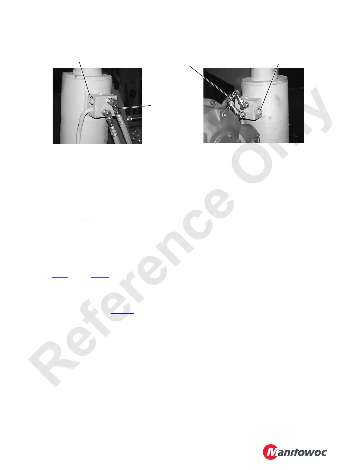
FIGURE 2-27
Rod End Counterbalance Valve
(with lock nut and adjusting screw)
View A
Gantry Cylinder
Right Rear Corner of Rotating Bed
P977
View B
Gantry Cylinder
Left Rear Corner of Rotating Bed
P976
Piston End
Counterbalance Valve
(with lock nut and
adjusting screw)
On Inboard Side
Rod End Counterbalance Valve
(with lock nut and adjusting screw)
On Inboard Side
Piston End
Counterbalance Valve
(with lock nut and adjusting screw)
 Loading...


