Manitowoc Published 07-19-16, Control # 249-01 1-97
2250 SERVICE/MAINTENANCE MANUAL INTRODUCTION
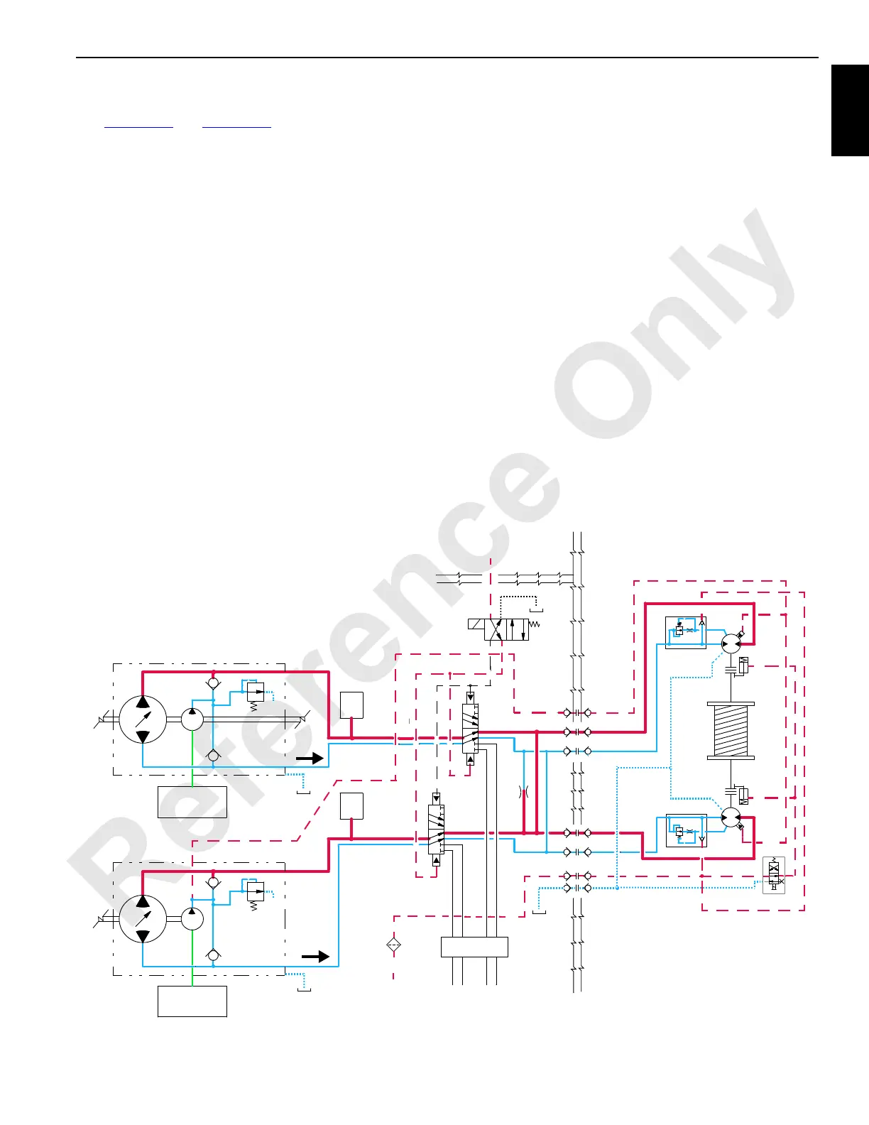
Drum 9 Lowering (MAX-ER Mode)
See Figure 1-63 and Figure 1-64 for the following.
When the left control handle (drum 9) is moved forward to
(lower), the handle neutral switch closes, sending an output
voltage of 5 V or less to the crane’s PC. The PC sends an
output signal to shift the diversion solenoid valve HS-54 to
allow the fluid to flow from the crawler’s travel pumps through
the diverting valve to the drum 9 motors.
The crane’s PC sends a negative output signal to stroke the
crawler’s travel pumps momentarily in the RAISE direction to
satisfy pressure memory. The PC compares drum-holding
pressure to the value stored in pressure memory. When
system pressure is high enough, the PC sends a positive
output signal to enable the brake solenoid HS-56. The brake
solenoid shifts to block the tank port and opens the port to
system charge pressure to release the brake.
The PC sends a positive output signal to stroke each crawler
travel pump’s EDC in the lower direction and a positive
output signal to each motor’s PCP. The crane’s PC checks
that the block-up limit switches are closed with no other
system operating limits present.
The crane’s PC sends a negative output voltage to each
pump’s EDC that tilts the pump’s swashplate in the LOWER
direction. Hydraulic fluid at system pressure up to 407 bar
(5,900 psi) maximum flows from pump ports B to port B of
the motors. Fluid from motor ports A returns to pump ports A.
The load weight attempts to drive the motors faster than
return fluid is available to the pumps. The system charge
pump maintains fluid supply at a positive pressure to the
motors. The position of each pump’s swashplate restricts the
returning fluid flow. Pressure builds on the return fluid side of
the closed-loop system, acting as a brake against the motors
to control the lowering speed.
The crane’s PC controls the lowering speed by varying the
voltage sent to the EDCs in relation to the left control
handle’s movement to program requirements. Each pump’s
swashplate angle is increased as the handle is moved
forward. As more fluid is returned to the pumps, more fluid is
pumped to the motors, and the drum lowers the load faster.
When the left control handle is moved to the neutral position,
the crane’s PC sends an output signal to the travel pump’s
EDCs to decrease the swashplate angle, reducing oil flow
output. The crane’s PC stores the load-holding pressure in
pressure memory. After the control handle’s neutral switch
opens, the PC sends an output signal to disable the brake
solenoid HS-56 to apply the brake before the crawler travel
pumps de-stroke.
24 bar
(350 psi)
Right Travel Pump
Left Travel Pump
To Travel
Motors
T
T
HS54
RM-20
A
B
A
B
HS56
Crane
Drum 9
24 bar
(350 psi)
Swivel
Suction
Manifold
Suction
Manifold
Hoist Charge Pump
A
B
B
A
Boom
UP
DOWN
DOWN
UP
From Boom
Flow
Flow
Brake Line
from
Fan Circuit
Servo Line
FIGURE 1-64
 Loading...


