INTRODUCTION 2250 SERVICE/MAINTENANCE MANUAL
1-96
Published 07-19-16, Control # 249-01
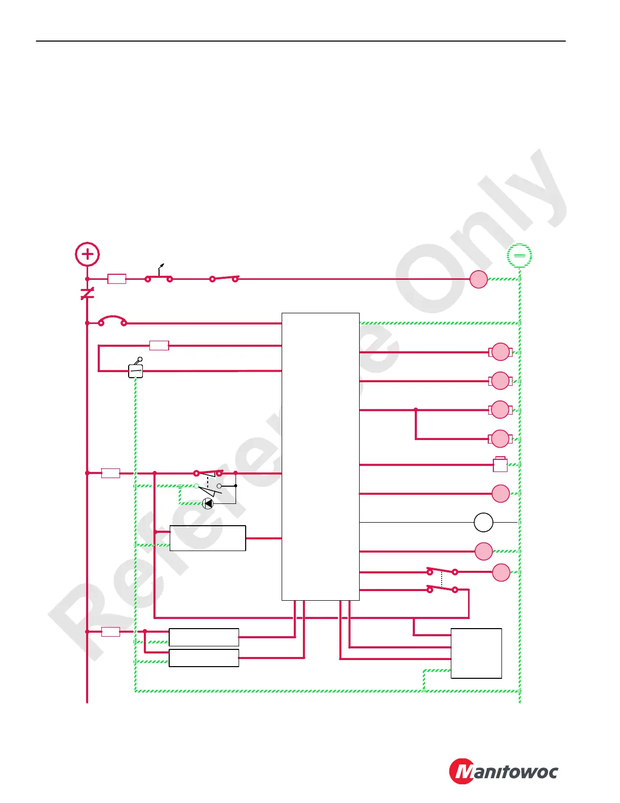
The crane’s PC controls raising speed by varying the voltage
to both pumps’ EDC and motor’s PCP in relation to the
handle’s movement. As the handle is moved back (RAISE),
the crane’s PC sends a signal to increase the pump’s
swashplate angle. The crane’s PC also sends a signal to the
motor’s servo to reduce the motor’s displacement. The
crane’s PC is continuously balancing the system pressure
and the motor’s displacement angle so the motor’s
displacement goes to minimum when the handle is all the
way back, if torque requirement on the motors is not too high.
Knowing the displacement of the motors, the crane’s PC may
then control the speed that the motors turn by regulating the
flow through the pumps.
When the left control handle is moved to the neutral position,
the crane’s PC sends an output signal to the travel pump’s
EDCs to decrease the swashplate angle, reducing oil flow
output. This shifts the motor’s servos back to maximum
displacement for slower output speed to slow the drum’s
rotation. The crane’s PC stores the load-holding pressure in
pressure memory. After the control handle’s neutral switch
opens, the PC sends an output signal to disable the brake
solenoid HS-56 to apply the brake before the travel pumps
de-stroke.
Left Handle Control
Left Travel
Sender
Right Travel
Sender
LOWERRAISE
Regulated 10V Out
5A
OFF
3A
8T
88MC
RM19
Drum 9
Flange
Encoder
80N
A
B
A
B
Drum 9 Left
Motor Control
Drum 9 Right
Motor Control
84A
83A
Right Travel
Pump Control
Left Travel
Pump Control
A
B
B
A
Left Control
Rotation Indicator
88D
Travel/Drum 9
Diverting Valve
AS
Drum 9
Brake
Pawl In
Pawl Out
88C
88CA
88E
88N
83DS
8K
84DS
87FA
80P
5DA
5A
Cab Power
OFF
ON
D
B
A
F
8P1
0
K1
50 Amp
0
10A
5D
5A
88MB
Drum 9
Minimum
Bail Limit
88MA
Engine
RUN/STOP
89G4
EDC
PCP
PCP
EDC
HS
54
HS
56
AS
22
21
Drum 9
Drum 9
K1
Crane
Programmable
Controller
FIGURE 1-63
90QM
Mast
Accumulator
Sender
F15
F12

 Loading...


