Manitowoc Published 07-19-16, Control # 249-01 1-27
2250 SERVICE/MAINTENANCE MANUAL INTRODUCTION
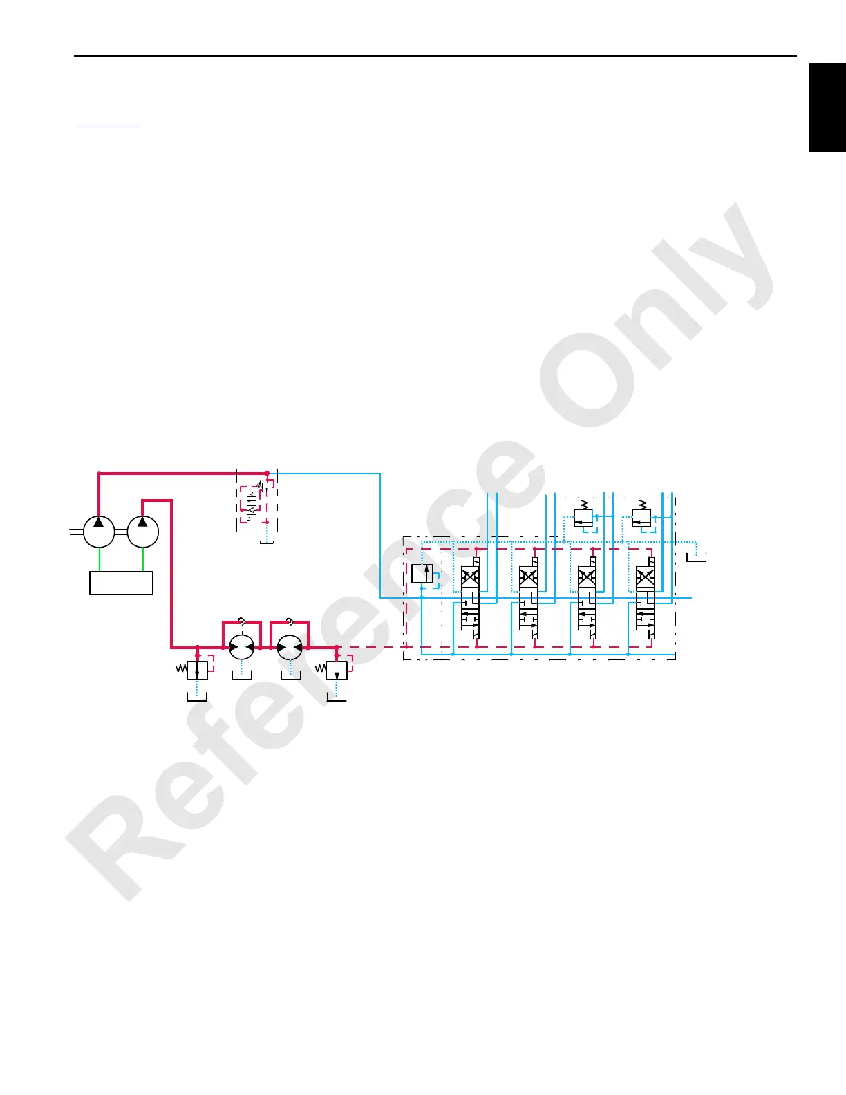
Accessory Systems
See Figure 1-12 for the following.
The auxiliary pump obtains fluid from the hydraulic tank
through the suction manifold. The auxiliary pump supplies
fluid to all of the hydraulic cylinder systems. Fluid flow is from
the accessory pump through the auxiliary system’s disable-
relief valve HS-12, upper accessory valve, proportional flow
control valve, and to the lower accessory valve.
When the auxiliary system is disabled, the auxiliary system’s
disable-relief valve HS-12 is opened. Hydraulic fluid from the
auxiliary pump then returns directly to the tank. The auxiliary-
system disable-relief valve also protects the auxiliary pump,
the down-stream components from excessive wear that
higher pressures can cause, and reduces power demand on
the engine.
When a component of the auxiliary system is enabled, the
auxiliary system’s disable-relief valve HS-12 shifts to block
the flow to the tank. Accessory system pressure builds up to
276 bar (4,000 psi), allowing the fluid to flow through the
auxiliary system disable-relief valve.
The suction manifold supplies hydraulic fluid to the fan
pump. The fan pump supplies hydraulic fluid to drive the two
fan motors. The fan’s relief valve protects the fan pump and
two fan motors from damage by limiting the fan’s system
pressure to 276 bar (4,000 psi). System pressure after the
fans are limited by a relief valve to 21 bar (300 psi) for pilot
pressure or fluid return to the tank.
The upper accessory function includes the following:
• Rotating bed jacking cylinders (qty 4)
• Front and rear adapter frame pin cylinders (qty 4)
• Gantry raising cylinders (qty 2)
The lower accessory function includes the following:
• Boom hinge pin cylinders (qty 2)
• Boom butt handling cylinder
• Rigging winch drum motor
• Crawler frame pins (qty 2)
To L o w e r
Suction
Manifold
M104180
Auxiliary Pump
Fan Pump
8
8
8
8
21 bar
(300 psi)
276 bar
(4,000 psi)
x
Accessory
Valve
Fan Circuit
Upper Accessory Valve
Pilot
Pressure
HS12
Valve
Disable-Relief
Auxiliary System
FIGURE 1-12
 Loading...


