Manitowoc Published 07-19-16, Control # 249-01 10-37
2250 SERVICE/MAINTENANCE MANUAL TROUBLESHOOTING
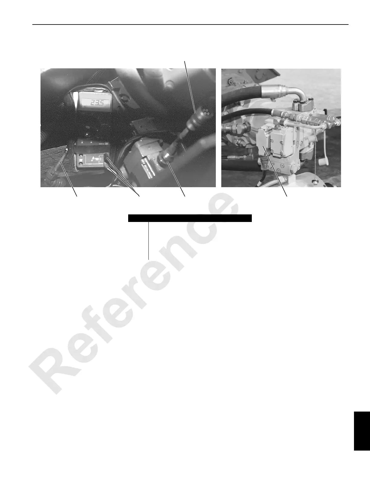
Test 4—Testing the Pump EDC and Motor PCP
Testing a pump electric displacement control (EDC) (3) or
motor pressure control pilot (PCP) (5) requires a standard
test plug adapter (4) (can be ordered from Manitowoc
Cranes) and a digital multimeter. To test a pump function,
proceed as follows.
1. Disconnect the PC input cable (1) from the pump EDC to
be tested.
2. Connect the double-ended test plug adapter EDC.
3. Leave the PC end of the test plug disconnected.
4. Set the digital multimeter for testing resistance.
5. Connect the white (positive) and black (negative) wires
from the adapter cable to the digital multimeter jacks.
6. Make sure the EDC resistance is between 15 and 19
ohms.
Leave the test plug adapter installed at the pump EDC and
proceed as follows.
1. Set the digital multimeter for testing volts DC.
2. Connect the PC input cable to the PC end of the test
plug adapter.
3. With the engine running, slowly enable the test system
control handle.
4. Make sure the range of voltage change is between 0 and
+/-2.45 volts DC.
5. Measure the load current by connecting the red and
white wires from the adapter cable to the digital
multimeter jacks.
To test motor function, remove the PC input line from the
motor PCP and connect the test plug adapter. Perform the
resistance and voltage tests as described for the pump EDC.
The motor PCP coil resistance should be between 23 and 26
ohms. The voltage should be between 0 and 1.96 volts DC.
P1531P1530
1
2
3
4
5
FIGURE 10-5
Item Description
1 PC Input Cable
2 Adapter Cable Connections
3 Pump Electric Displacement Control (EDC)
4 Test Plug Adapter
5 Motor Pressure Control Pilot (PCP)
 Loading...


