TROUBLESHOOTING 2250 SERVICE/MAINTENANCE MANUAL
10-50
Published 07-19-16, Control # 249-01
Test 16—Checking the Pump Charge Pressure and Electrical Test
Component charge systems can be checked at the M1, M2,
or M3 gauge ports (see Test 6—Location of Motor Ports
). To
check the pump charge pressure, perform the following
procedure.
1. Install a 0 to 42 bar (0 to 600 psi) gauge at the desired
system diagnostic gauge coupler on the pressure
transducer manifold.
2. Start the system and record the charge pressure at
engine idle speed.
No hydraulic systems should be enabled.
A reading of 24 bar (350 psi) is the system charge
pressure.
A reading of less than 24 bar (350 psi) indicates a
charge pressure relief adjustment is necessary. See
Test 18—Adjusting the Pump Charge Pressure Relief
.
Test the voltage and resistance of a system pressure
transducer with a standard test plug adapter (can be ordered
from Manitowoc Cranes) and a digital multimeter.
To test the incoming power at the desired pressure
transducer, perform the following procedure.
1. Connect the test plug adapter between the pressure
transducer (9) and the DIN connector (8).
2. Connect the white (positive) and black (negative) wires
from the adapter cable to the digital multimeter jacks.
3. Check for 12 volts DC.
4. If this reading is not obtained, check the 5 amp F12 fuse
at the fuse panel (see Test 11—Testing for Voltage at the
Fuse Box).
To test voltage output from the pressure transducer to the
PC, perform the following procedure.
1. Make sure the engine is off and the power is on, with all
brakes and locks engaged.
2. Connect the green (positive) and black (negative) wires
to the digital multimeter jacks.
3. Check for 1.00 to 1.04 volts DC.
The PC null or zero routine permits the pressure transducer
to operate outside the above voltage range. If the reading is
less than 0.50 volts or more than 2.00 volts, the pressure
transducer must be replaced.
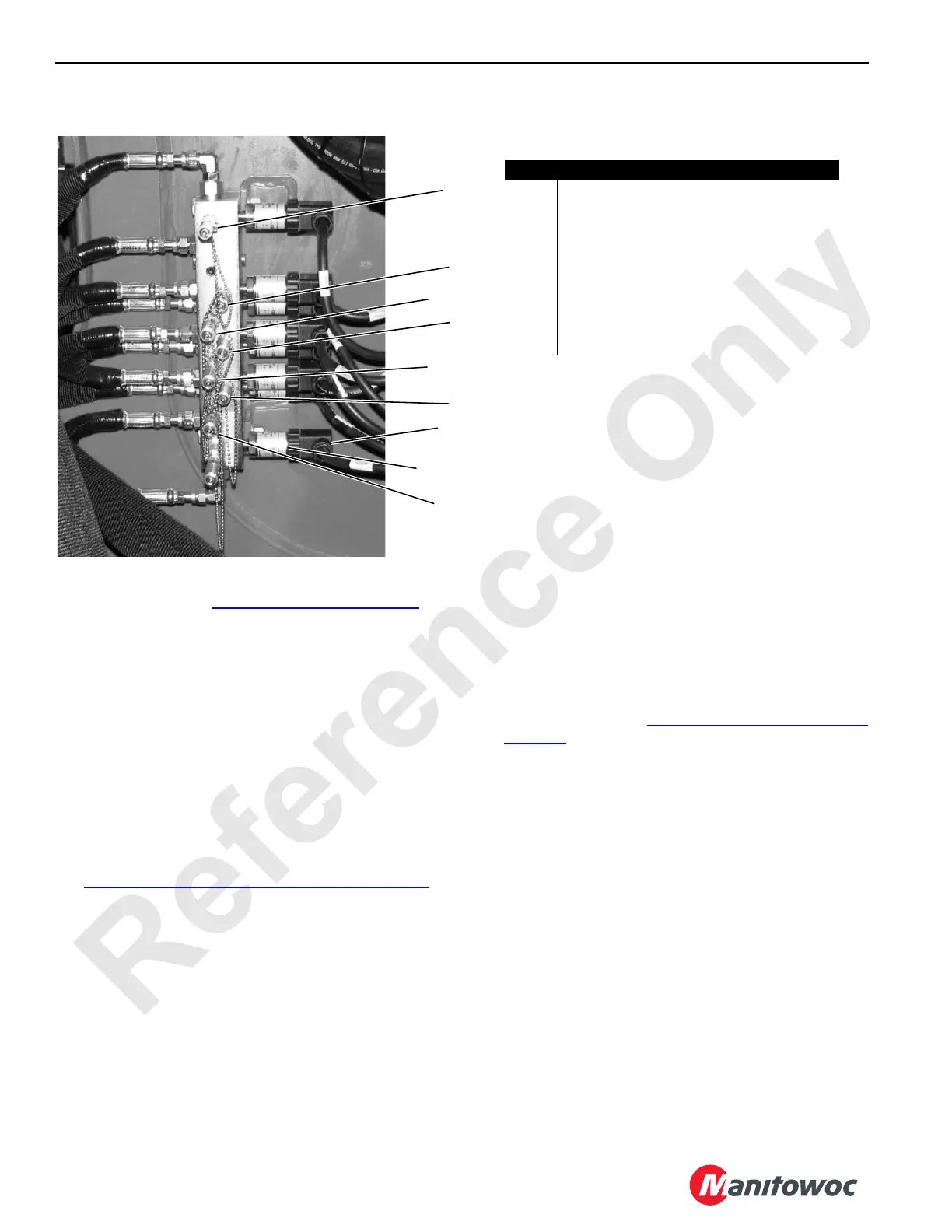
P6706
Item Description
1 Right Travel System Pressure Port
2 Boom Hoist System Pressure Port
3 Hoist System Pressure Port (pump out-board)
4 Hoist Charge Pressure Port (pump in-board)
5 Swing Right System Pressure Port
6 Swing Left System Pressure Port
7 Left Travel Charge Pressure Port
8 DIN Connector (electrical test)
9 Pressure Transducer
1
2
3
4
5
6
7
8
9
FIGURE 10-18

 Loading...


