Manitowoc Published 07-19-16, Control # 249-01 10-49
2250 SERVICE/MAINTENANCE MANUAL TROUBLESHOOTING
To determine if a hydraulic solenoid is enabled, place a
screwdriver on the solenoid coil. The solenoid is enabled if
the screwdriver is magnetically pulled toward the solenoid
coil.
Measure the system voltage at various locations on the
hydraulic valve assemblies with a standard test plug adapter
(can be ordered from Manitowoc Cranes) and a digital
multimeter.
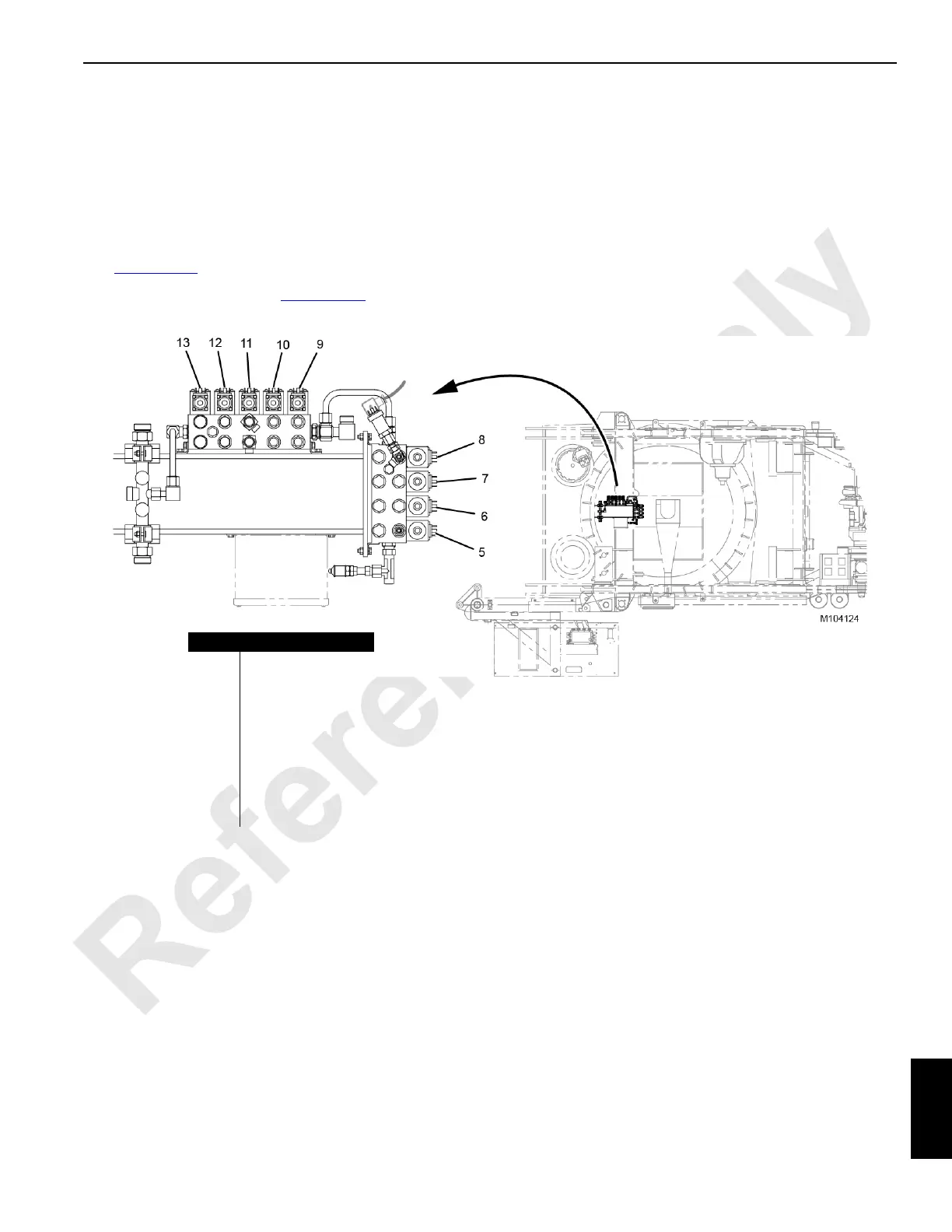
See Figure 10-17
for identification of the valves.
To test a hydraulic valve, see Figure 10-16
and perform the
following procedure.
1. Set the digital multimeter for testing volts DC.
2. Connect the white (positive) and black (negative) wires
from the adapter cable to the digital multimeter jacks.
3. Install the test plug between the valve electrical socket
and the DIN plug (1).
4. Enable the valve being tested.
5. Check for 12 volts DC at the upper valve assembly (3)
and the auxiliary system disable valve (4).
Voltage to the proportional flow control valve (2) should
be between 3.25 and 7.22 volts DC.
Item Description
5 Luffing Hoist Brake
6 Travel 2 Speed
7Travel Brake
8Swing Brake
9 Left Crawler Pins
10 Right Crawler Pins
11 Boom Hinge Pins
12 Boom Butt Handling
13 Rigging Winch
FIGURE 10-17
 Loading...


