ELECTRICAL SYSTEM 2250 SERVICE/MAINTENANCE MANUAL
3-16
Published 07-19-16, Control # 249-01
MODEL 2250 MAX-ER 2000
®
TEST
VOLTAGES
General
This section contains MAX-ER 2000 test voltages sorted into
the following three categories:
• Pin identification
• Wire identification
• Description identification
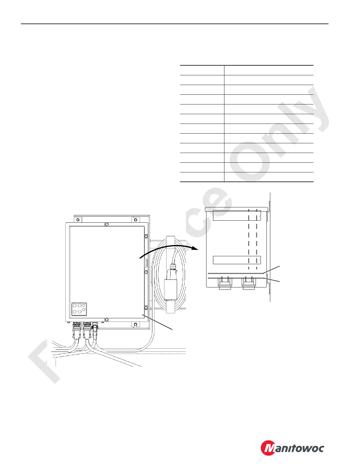
Controller Board Layout
The board locations in the MAX-ER 2000 programmable
controller are shown below.
Abbreviations
The following abbreviations are used in this section:
AI Analog Input
AO Analog Output
CHA or CHB Channel A or B
COMM Communication
CPU Central Processing Unit
DI Digital Input
DO Digital Output
I/O Input/Output
lb Pounds
N/C No Connection
Press Pressure
psi Pounds per Square Inch
CPU BOARD
I/O BOARD 1
Programmable Controller
Inside MAX-ER Junction Box
Mother
Board 2
Mother
Board 1
MAX-ER Junction Box
Left Side of Rotating Bed
FIGURE 3-7

 Loading...


