INTRODUCTION 2250 SERVICE/MAINTENANCE MANUAL
1-94
Published 07-19-16, Control # 249-01
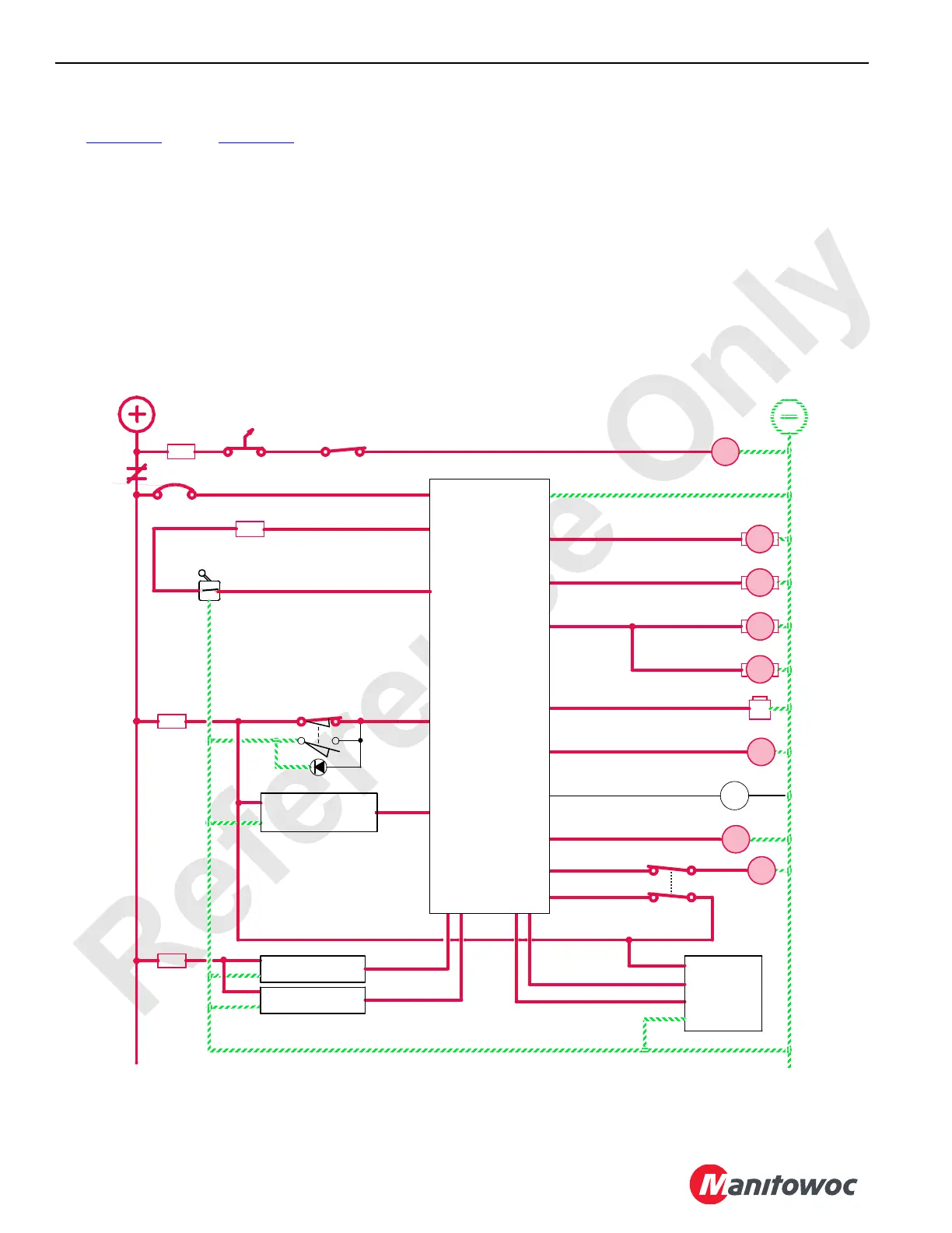
Drum 9 Operation
See Figure 1-61 through Figure 1-64 for the following.
For MAX-ER configurations, drum 9 is mounted in the boom
butt. The source of pressurized hydraulic fluid to operate
drum 9 is from the crane’s crawler travel system or boom
hoist system depending on the crane’s program version.
The left control handle controls the drum 9 operation. The
corresponding number 9 green light comes on behind the left
control handle. The programmable controller (PC) applies
the drum 9 brakes, controls the crawler travel pump’s speed,
and selects the control handle operation depending on the
crane’s mode version. See Section 3 of MAX-ER Operator
Manual for MAX-ER operation.
The motor loop flushing valves open when system pressure
exceeds 14 bar (200 psi). The sequence/flow control valve
removes 15 L/min (4 gpm) of hot fluid from the system by
dumping the fluid in the motor’s case where it returns to the
tank.
When drum 9 is operating, the PC monitors input signals
from the crawler travel pressure senders and adjusts the
motor’s displacement to maintain equal pressure.
The drum-flange-mounted speed sender monitors drum
speed and controls drum overspeed. The speed sender
sends a signal to the crane’s PC that enables the rotation
indicator in the drum’s control handle. This indicator pulsates
with a varying frequency depending on the drum’s rotational
speed.
Left Handle Control
Left Travel
Sender
Right Travel
Sender
LOWERRAISE
Regulated 10 V Out
5A
OFF
3A
8T
88MC
RM17
Drum 9
Flange
Encoder
80N
A
B
A
B
Drum 9 Left
Motor Control
Drum 9 Right
Motor Control
84A
83A
Right Travel
Pump Control
Left Travel
Pump Control
A
B
B
A
Left Handle
Rotation Indicator
88D
Travel/Drum 9
Diverting Valve
Brake
Pawl In
Pawl Out
88C
88CA
88E
88N
83DS
8K
84DS
87FA
80P
5DA
5A
Cab Power
OFF
ON
D
B
A
F
8P1 0
K1
50 Amp
0
10A
5D
5A
88MB
Drum 9
Minimum
Bail Limit
88MA
Engine
RUN/STOP
89G4
HS
56
EDC
EDC
PCP
PCP
HS
54
Drum 9
AS
21
AS
22
Drum 9
Drum 9
K1
Programmable
Controller
FIGURE 1-61
90QM
Mast
Accumulator
Sender
F12
F15
 Loading...


