INTRODUCTION 2250 SERVICE/MAINTENANCE MANUAL
1-22
Published 07-19-16, Control # 249-01
Hydraulic Components
See Hydraulic and Air Systems Section 2 for the hydraulic
schematic.
High-pressure piston pumps driven by a multi-pump drive
provides independent closed-loop hydraulic power for the
crane’s functions. Each system is equipped with relief valves
to protect for overload or shock.
Each hydraulic solenoid valve is assigned an hydraulic
solenoid (HS) number. The HS number identifies each
hydraulic solenoid valve.
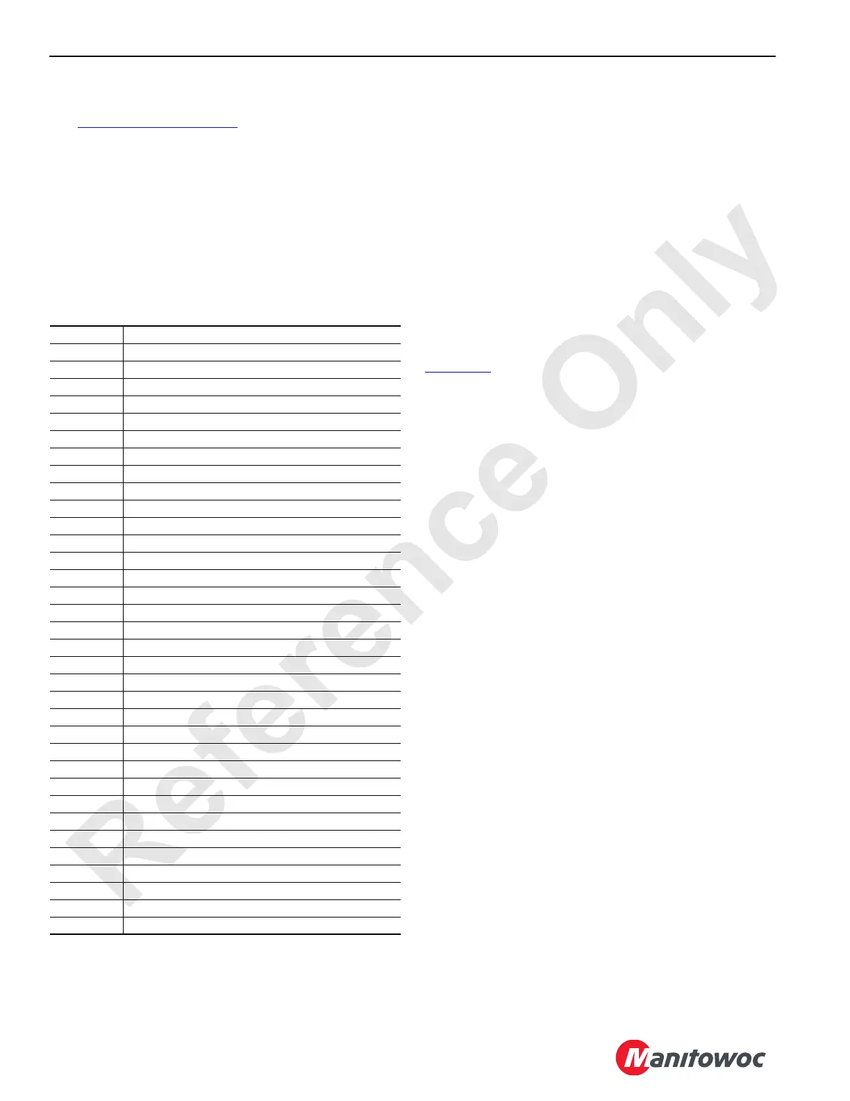
Table 1-1. Hydraulic Solenoid (HS) Valves
Hydraulic Tank
The hydraulic tank has a vented fill cap, high and low level
sight gauge, vacuum sensor, temperature sensor, and fluid
level sensor. The digital display indicates temperature and
pressure (vacuum) of the fluid in the reservoir. Hydraulic fluid
vacuum is displayed as a pressure between 0.5 and 1.2 bar
absolute (7 and 18 psi) depending on engine speed, ambient
temperature, and filter condition. The breather protects the
tank from excessive pressures by opening at 0, 20 bar
(3 psi), or the vacuum opens at 38 mm HG (1.5 in HG).
The hydraulic tank has two sections, a suction section and a
return section. The suction section has a 100-micron mesh
strainer that allows fluid to bypass the strainer at 0,31 bar
(4.5 psi) if it becomes plugged. Two spin-on filters also filter
the fluid. Replace the filter elements when a pressure of
0,5 bar absolute (7 psi) is shown on the digital display.
The return section inlets are routed through the check
valves. A diffuser inside the tank’s return line reduces
turbulence created by the fluid returning to the tank. See
Lubrication
Section 9 for recommended replacement of the
hydraulic fluid.
Shut-off Valve
A manual shut-off valve is located between the hydraulic
tank and the suction manifold. Close the shut-off valve when
performing maintenance on the hydraulic systems. Open the
shut-off valve before starting the engine.
Suction Manifold
The suction manifold supplies fluid to the system pumps. A
line between the suction side of the tank and the suction
manifold has a shut-off valve. When the shut-off valve is
open, fluid flows from the tank through the valve to the
suction manifold. The suction manifold distributes fluid to the
charge pumps of the six main system pumps, auxiliary pump,
and fan pump.
Return Manifolds
Fluid from the closed-loop relief valves, brake valves, motor
servos, cylinders, fan drive, pump case drain, and motor
case drain is routed to the main return manifold or the cooler
return manifolds before returning to the hydraulic tank.
Hydraulic Fluid Cooler
To control hydraulic fluid temperature, return fluid from some
of the component systems returns to the tank through the
cooler. A 1,4 bar (20 psi) bypass valve shifts to allow the fluid
to flow around the cooler if it becomes plugged.
Hydraulic Pumps
See Sauer-Sundstrand Series 90 Service Manual for a
description of a hydraulic piston pump.
The pump’s displacement depends on the engine-driven
pump’s speed and the swashplate’s tilt angle. The engine
provides power for work, while the swashplate’s tilt angle
provides speed control. Engine speed is set and controlled
with the hand or foot engine throttle.
HS-1 Travel Brake
HS-2 Left Crawler Frame Pins Engage
HS-3 Left Crawler Frame Pins Disengage
HS-4 Gantry Cylinders Extend
HS-5 Gantry Cylinders Retract
HS-6 Boom Hoist (drum 4) Brake
HS-7 Swing Brake
HS-8 Not Used
HS-9 Not used
HS-10 Boom Hinge Pins Engage
HS-11 Boom Hinge Pins Disengage
HS-12 Auxiliary System Disable-Relief
HS-13 Right Crawler Frame Pins Engage
HS-14 Right Crawler Frame Pins Disengage
HS-15 Boom Butt Handling Cylinder Extend
HS-16 Boom Butt Handling Cylinder Retract
HS-17 Rigging Winch Haul In
HS-18 Rigging Winch Pay Out
HS-19 Luffing Jib Hoist Drum Brake
HS-20 Variable Output Control (proportional)
HS-21 Front Adapter Frame Pins Engage
HS-22 Front Adapter Frame Pins Disengage
HS-23 Rear Adapter Frame Pins Engage
HS-24 Rear Adapter Frame Pins Disengage
HS-25 Left Front Jack Extend
HS-26 Left Front Jack Retract
HS-27 Right Front Jack Extend
HS-28 Right Front Jack Retract
HS-29 Left Rear Jack Extend
HS-30 Left Rear Jack Retract
HS-31 Right Rear Jack Extend
HS-32 Right Rear Jack Retract
HS-33 Hydraulic Quick Disconnect Engage
HS-34 Hydraulic Quick Disconnect Disengage
HS-35 Travel 2-Speed

 Loading...


