Manitowoc Published 07-19-16, Control # 249-01 2-41
2250 SERVICE/MAINTENANCE MANUAL HYDRAULIC AND AIR SYSTEMS
Maintenance
See Figure 2-45 for the following procedure.
Maintenance periods should be scheduled in accordance
with the frequency of use and working conditions of the
valve.
One complete valve should be kept in stock for each four
valves in service. During the maintenance period, change
out the complete valve with the standby unit. This will reduce
production time loss and allow inspection and replacement
of worn parts in a clean location at a more convenient time.
NOTE: The operating portion of the valve can be removed
without disturbing the pipe connections.
No special tools are required to maintain the valve.
1. Remove the valve portion by loosening the nut (5) and
stud (6).
2. Completely disassemble the valve.
3. Wash all metal parts in a nonflammable solvent and all
rubber parts in soap and water.
4. Rinse each part thoroughly and blow dry them with a
low-pressure air jet.
5. Arrange the parts on a clean surface in the order of the
exploded view.
6. Examine each part carefully. Flex the diaphragm and
packing rings, and if cracked or worn, replace them.
Replace all parts that may not provide satisfactory
service until the next maintenance period.
7. Reassemble the valve using the exploded view as a
guide. Lubricate each part before it is put into place. Use
No. 107 Lubriplate on all metal-to-metal surfaces and
No. 55 Pneumatic Grease on all rubber parts. Equivalent
greases to those recommended can be used.
8. Store the reconditioned valve in a moisture-proof bag.
Adjustments
See Figure 2-45 for the following procedure.
Use the adjusting screw (7) to adjust the valve. Turn the
adjusting screw in to raise the outlet pressure, and turn it out
to lower the outlet pressure.
S120
9
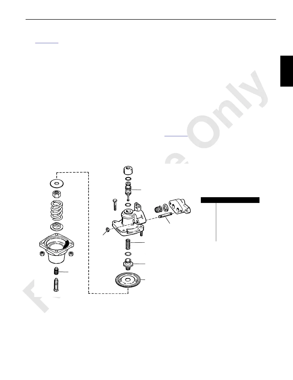
FIGURE 2-45
Item Description
1 Exhaust Valve Unit
2 Control Spring
3 Diaphragm
4 Exhaust Valve Seat
5Nut
6Stud
7 Adjusting Screw
1
2
3
4
5
6
7
 Loading...


