INTRODUCTION 2250 SERVICE/MAINTENANCE MANUAL
1-46
Published 07-19-16, Control # 249-01
When the control handle moves toward the neutral position,
the PC compensates for system leakage or changing engine
speed. The PC sends a 0 V output to the pump’s EDC that
moves the swashplate to the center position. This shifts the
motor back to maximum displacement for slower output
speed to slow the drum’s rotation.
The PC stores the load-holding pressure in pressure
memory. After the control handle center switch opens, the
PC sends a 0 V output signal to the right rear brake solenoid
AS-9. The valve is disabled and shifts to block manifold air
pressure to the brake cylinder and apply the brake. The
brake applies before the drum pump de-strokes.
Lowering the Load Drum
When the right load drum control handle is moved forward
for lowering, an input voltage of 5 V or less is sent to the PC.
The PC sends a variable plus 0 to 2.8 V output that is applied
to both load drum pump’s EDC. The PC sends a variable 0 to
2.19 V output that is applied to the load drum motor’s
pressure-control pilot (PCP). The PC checks that the right
rear maximum bail and block-up limit switches are closed
and that there are no faults in the air or hydraulic system.
The PC sends a 12 V output signal to enable the front drum
clutch solenoid AS-8 and left-rear drum clutch solenoid AS-
12. The valves shift to allow manifold air pressure to flow to
the clutch cylinders and compress the springs to release the
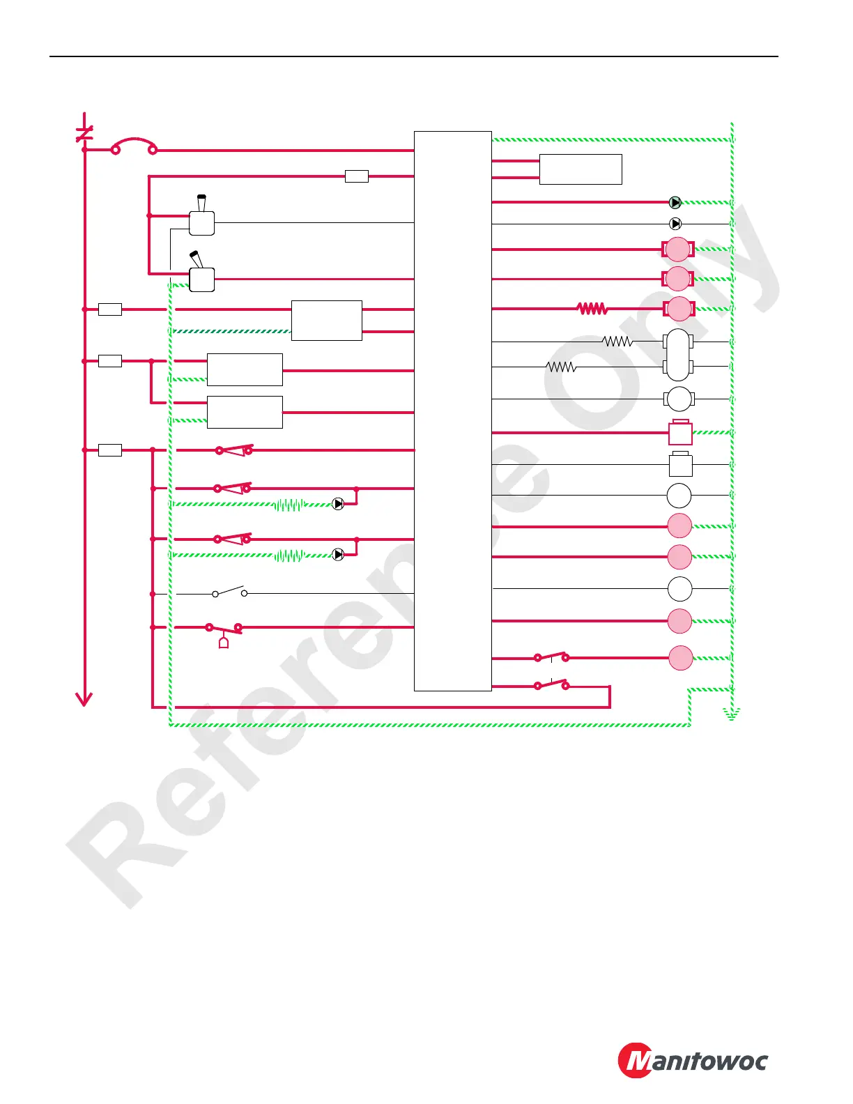
RF-20
50 Amp
8P1
10 V Regulated Supply
WA-03
WA-01
Left (drum 1) Control Handle
K1
8
Raise
5A
F16
3A
Lower
F11
5A
8E
Crane Display
WD-19
WD-20
WC-05
Main Pump Control 1
EDC
B
A
0
Ground
Main Charge
Pressure
Sender
WA-25
WA-22
WE-04
WE-03
8E
0
AS
19
87FA
Drum 2 Pawl In
WE-36
WA-04
Right (drum 2/3) Control Handle
Raise
Lower
Main Hoist
Pressure
Sender
Right Rear
Speed
Sender
F
A
B
D
(drum 2)
Minimum Bail Limit (drum 2)
WB-08
Maximum Bail Limit (drum 2)
WB-07
WC-06
Main Pump Control 2
EDC
B
A
WD-25
Main Hoist Motor Control
PCP
B
A
WC-26
Left Rotation Indicator
AS
20
Drum 2 Pawl Out
WE-37
F10
8D
AS
9
WB-27
WC-08
Drum 2 Brake
Right Handle Drum 2 Light
WC-11
F12
5A
8E
WB-22Left Rear Drum
WD-20
Low Air Pressure
Has No Function
WD-36
Amber
WC-20
Opt. Main Pump Control
B
A
WC-29
C
D
P/C
Green
WD-34
Opt. Main Motor Control
PCP
B
A
AS
10
Drum 2 Clutch
WC-17
AS
8
Drum 1 Clutch
WC-16
AS
12
Drum 3 Clutch
WC-18
Controller
Programmable
5A
Seat Switch
WB-10
WC-33
Right Rotation Indicator
FIGURE 1-27
 Loading...


