Manitowoc Published 07-19-16, Control # 249-01 3-29
2250 SERVICE/MAINTENANCE MANUAL ELECTRICAL SYSTEM
Swing (crane)
1. The handle command in percent from neutral (+ right, –
left). For certain operating conditions, the handle
command is set to neutral by the controller even if the
handle is not in neutral.
2. The crane swing pump command in percent from neutral
(+ right, – left)
3. The measured pump pressure swing right (port B) in psi
4. The measured pump pressure swing left (port A) in psi
5. The measured swing brake pressure from 0 to 750 psi
6. MAX-ER 2000 shorting plug status:
0 = MAX-ER 2000 enabled
1 = MAX-ER 2000 shorting plug installed
7. MAX-ER 2000 travel status:
0 = Travel disabled
1 = Travel enabled
The MAX-ER 2000 travel status is determined by the
swing brake pressure and MAX-ER shorting plug status.
If the swing pressure is less than 150 psi and the MAX-
ER shorting plug is absent, travel is disabled.
8. Swing limiter sensor status (appears only if equipped
with a swing limiter):
+ = Swing right
- = Swing left
Track (crane crawlers)
1. The right handle command in percent from neutral (+
forward, – backward). For certain operating conditions,
the handle command is set to neutral by the controller
even if the handle is not in neutral.
2. The right pump command in percent from neutral (+
forward, – backward)
3. The left handle command in percent from neutral (+
forward, – backward. For certain operating conditions,
the handle command is set to neutral by the controller
even if the handle is not in neutral.
4. The left pump command in percent from neutral (+
forward, – backward)
5. The measured system pressure right track in psi
6. The measured system pressure left track in psi
7. The command to park break (1 release, 0 engage)
Mast Accumulator
1. The accessory disable valve stroke (0 to 100%)
2. Control requirement:
0 = No demand
1 = Accessory disable valve enable input
2 = MAX-ER wagon controls
3 = MAX-ER luffing jib stop cylinders
4 = Mast stop cylinders
3. The accumulator pressure in psi
4. The accessory pump pressure (will display if equipped)
MXR (MAX-ER 2000)
1. Counterweight level indicator:
+ = Degrees high on right side
- = Degrees low on left side
2. Backhitch load (US tons):
+ = Tension
- = Compression
3. MAX-ER switches (see below)
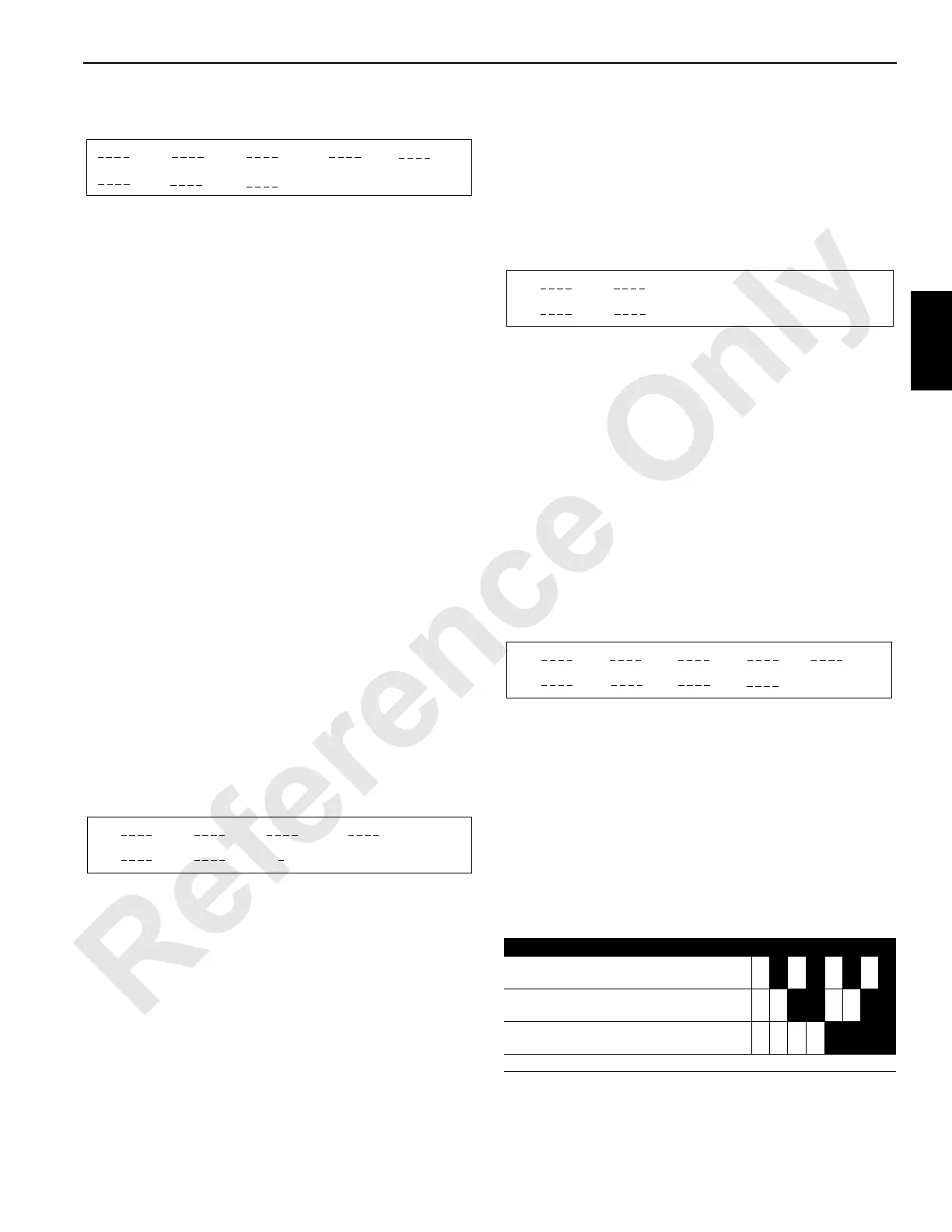
Table 3-6. MAX-ER Switches
SWING
1 2 3 4
6
7
5
8
FIGURE 3-18
Switches 0 1 2 3 4 5 6 7
Left strap cylinder limit switch (normally
closed)
Counterweight raise remote control switch
(normally open)
Counterweight lower remote control switch
(normally open)
Dark shaded boxes indicate ON, white boxes OFF.

 Loading...


