HOISTS 2250 SERVICE/MAINTENANCE MANUAL
5-16
Published 07-19-16, Control # 249-01
INSPECTING AND ADJUSTING THE DRUM
CLUTCH—STANDARD
Description
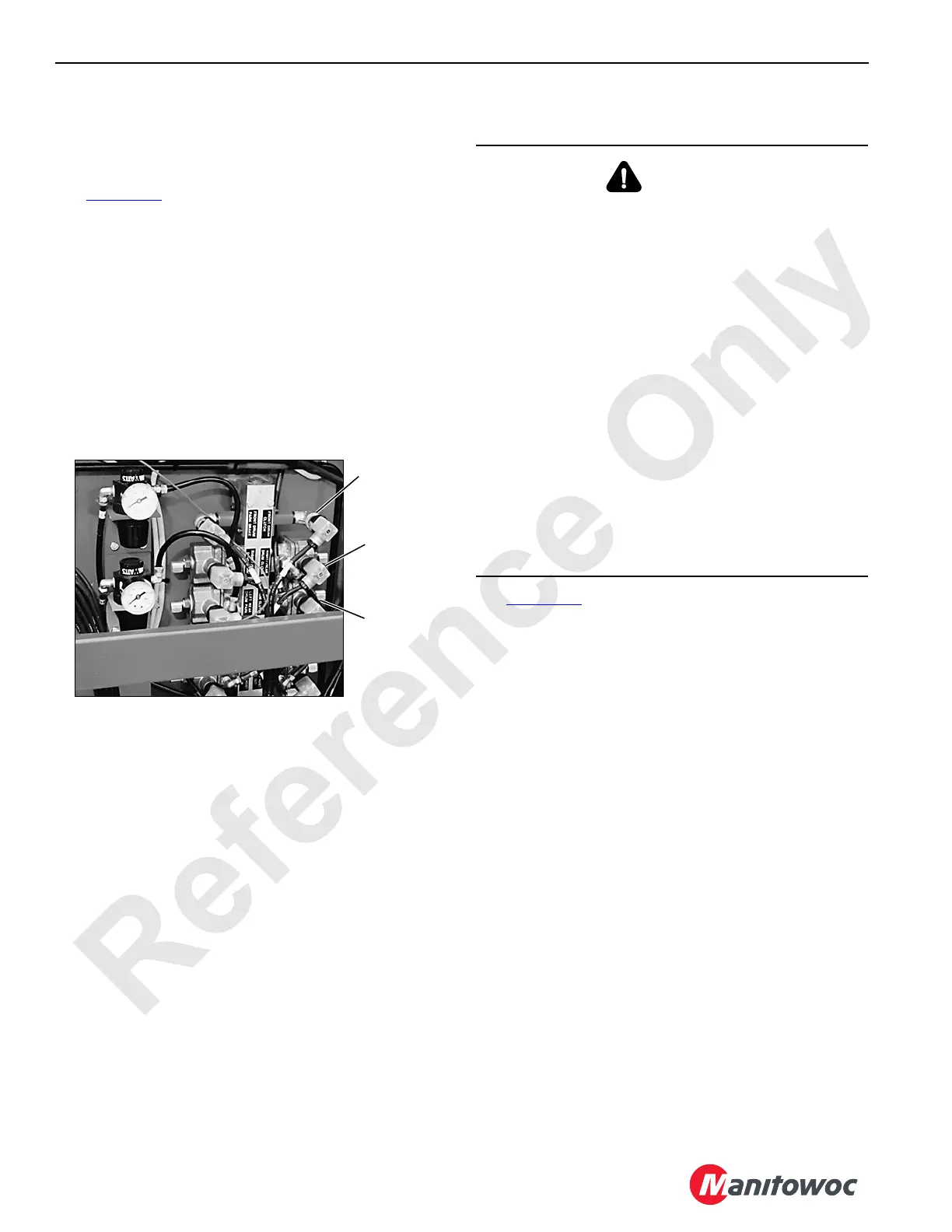
See Figure 5-13 for the following.
The drum clutch is an internal, expanding band-type clutch
that is spring-applied and air-released.
On a single drum shaft, the clutch is mounted on the left end
of the drum. On a split drum shaft, a clutch is mounted on the
outboard end of both drums. Each drum clutch is controlled
by a two-position (on/off) normally closed solenoid valve
located on the left side of the rotating bed.
A clutch access hole with a removable cover is provided in
the guard over each drum brake and clutch. Make all
inspections and adjustments when the clutch linings are
cold.
Inspection and Adjustment
See Figure 5-14 for the following procedure.
Make sure the air system pressure is 8,3 to 9,1 bar (120 to
132 psi) at all times during the inspection and adjustment
procedure.
1. Lower the load block or weight ball to the ground so the
wire rope is slack on the drum being serviced.
2. Select Standard mode and confirm.
3. To position the clutch parts in the access hole during the
inspection and adjustment steps, proceed as follows.
a. Remove the cover from over the access hole (2).
b. Stand clear of the clutch while the drum is turning.
c. Move the drum handle for the clutch being serviced
in either direction from the OFF position to turn the
clutch and drum.
d. When the desired part is accessible through the
access hole, have the adjuster signal the operator to
release the drum handle to the OFF position to stop
the clutch and drum.
4. Position the live end of the clutch band in the access
hole and inspect the lining (16) wear.
The clutch lining is 10 mm (3/8 in) thick when new.
Replace the lining before its thickness is less than 6 mm
(1/4 in), or the lining rivets will score the drum.
FIGURE 5-13
Left Rear
Drum Clutch
Solenoid Valves on
Left Side of Rotating Bed
P805
Front Drum
Clutch
(if equipped)
Rear or Right
Rear Drum
Clutch
CAUTION
Moving Machinery Hazard!
It is necessary to rotate the load drum and apply/release
the drum clutch during inspection, adjustment, and
overhaul procedures. This creates a condition in which, if
care is not exercised, minor injury or equipment damage
may occur.
Drum clutch inspection, adjustment, and overhaul
requires two people—one to operate the drum and brake
controls and one to perform the inspection, adjustment,
and overhaul procedures. Maintain constant
communication between the adjuster and operator so the
drum and brake are not operated while the adjuster is in
contact with moving parts.
Lower the load block or weight ball onto the ground so the
wire rope is slack on the drum being serviced.
• The adjuster shall stay clear of all moving parts while
the load drum and clutch are being operated.
• The operator shall not operate the drum controls until
the adjuster is clear of moving parts.

 Loading...


