HYDRAULIC AND AIR SYSTEMS 2250 SERVICE/MAINTENANCE MANUAL
2-4
Published 07-19-16, Control # 249-01
c. Thoroughly clean the fill cap and screen in a clean,
nonflammable solvent and blow dry the parts with
compressed air.
d. Replace the screen if it is damaged.
e. Install new gaskets if necessary.
f. Assemble the screen, gaskets, and flange to the
tank. Tighten the screws evenly.
g. Securely fasten the fill cap to the flange.
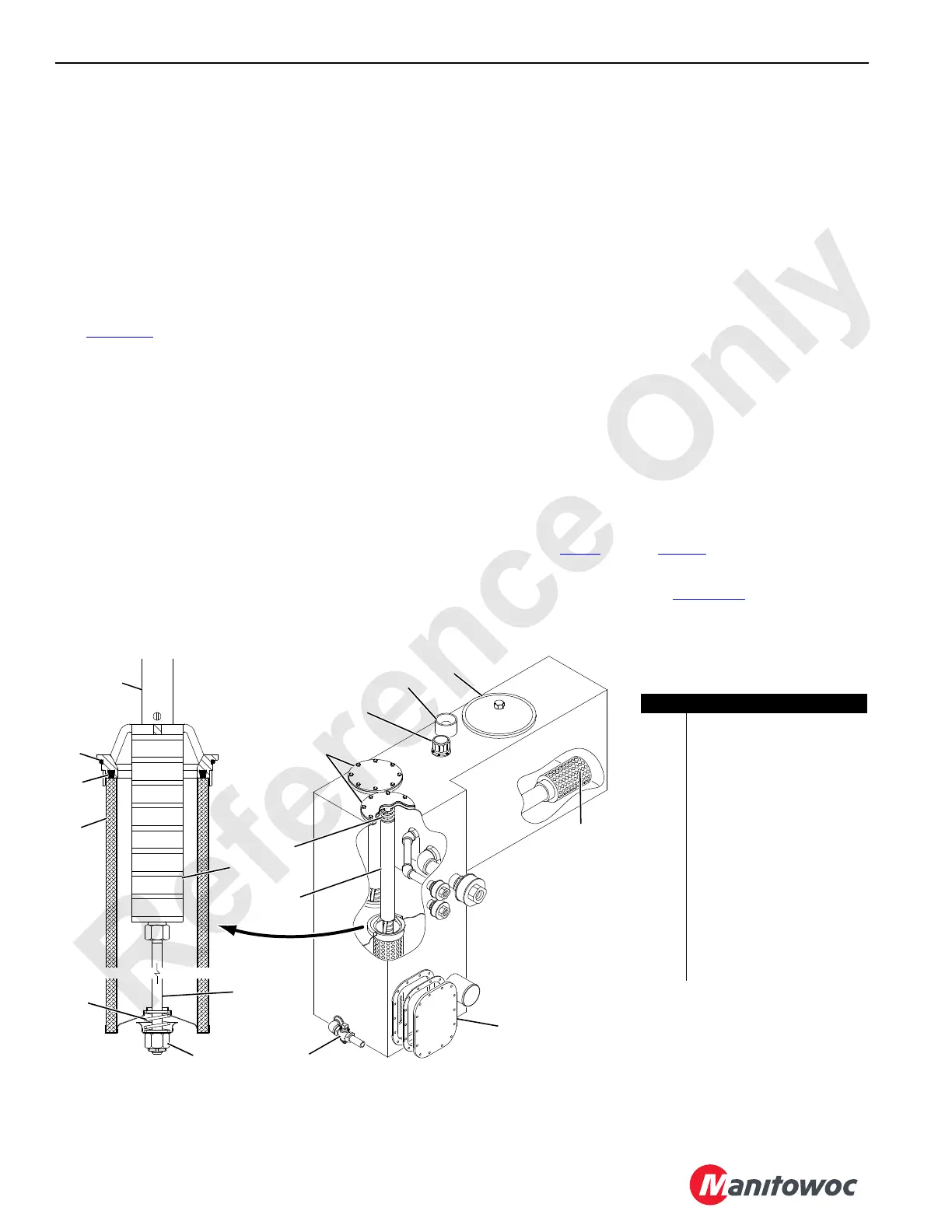
Replacing the Suction Filter Element
See Figure 2-3 for the following procedure.
The system faults alert will come on in the operator’s cab
when the filter elements are plugged with dirt. See Section 3
of the Operator Manual for more information.
Replace both elements when the alert comes on and at each
oil change.
NOTE: The hydraulic tank does not need to be drained to
replace the filter elements (except when changing
the oil).
1. Stop the engine.
2. Remove the filter access cover (6).
3. Remove the filter spring (5).
4. Lift the filter assembly out of the tank using the insert (4).
5. Remove the bypass spring (13).
6. Remove the filter element (14) by twisting it off and
discard.
7. Clean the magnetic core (10) with a lint-free cloth.
8. Check all seals (15) for damage and replace them if
necessary.
9. Lubricate the seals with clean hydraulic oil.
10. Install a new filter element.
NOTE: For ease of mounting, hold the element away from
the magnetic core until the stud (11) is through the
hole in the bottom of the element. Then slide the
element up to securely seat it with the top of the
filter housing.
11. Install the bypass spring assembly. Tighten the nut (12)
until snug.
12. Reinstall the filter assembly in the tank housing.
13. Reinstall the filter spring (5), gasket, and filter access
cover.
14. Evenly tighten the capscrews holding the cover in place.
15. Perform step 2
through step 14 for the other element.
16. Fill the hydraulic tank to the specified level with the
proper hydraulic oil (see Lubrication
Section 9). When
adding oil to the tank, filter the oil through a 10-micron
filter.
FIGURE 2-3
Hydraulic Tank
(right corner of rotating bed)
Suction Filter
(2 each)
A465
View A
View B
Item Description
1Diffuser (qty 2)
2 Clean-Out Cover
3Drain Valve
4 Insert (qty 2)
5 Filter Spring (qty 2)
6 Filter Access Cover (qty 2)
7 Fill Cap
8 Level Gauge
9 Clean-Out Cover
10 Magnetic Core (qty 2)
11 Stud (qty 2)
12 Nut (qty 2)
13 Bypass Spring (qty 2)
14 Filter Element (qty 2)
15 Seal (qty 4)
1
2
3
4
5
6
7
8
9
10
11
12
13
14
15
15
4
 Loading...


