RF-03
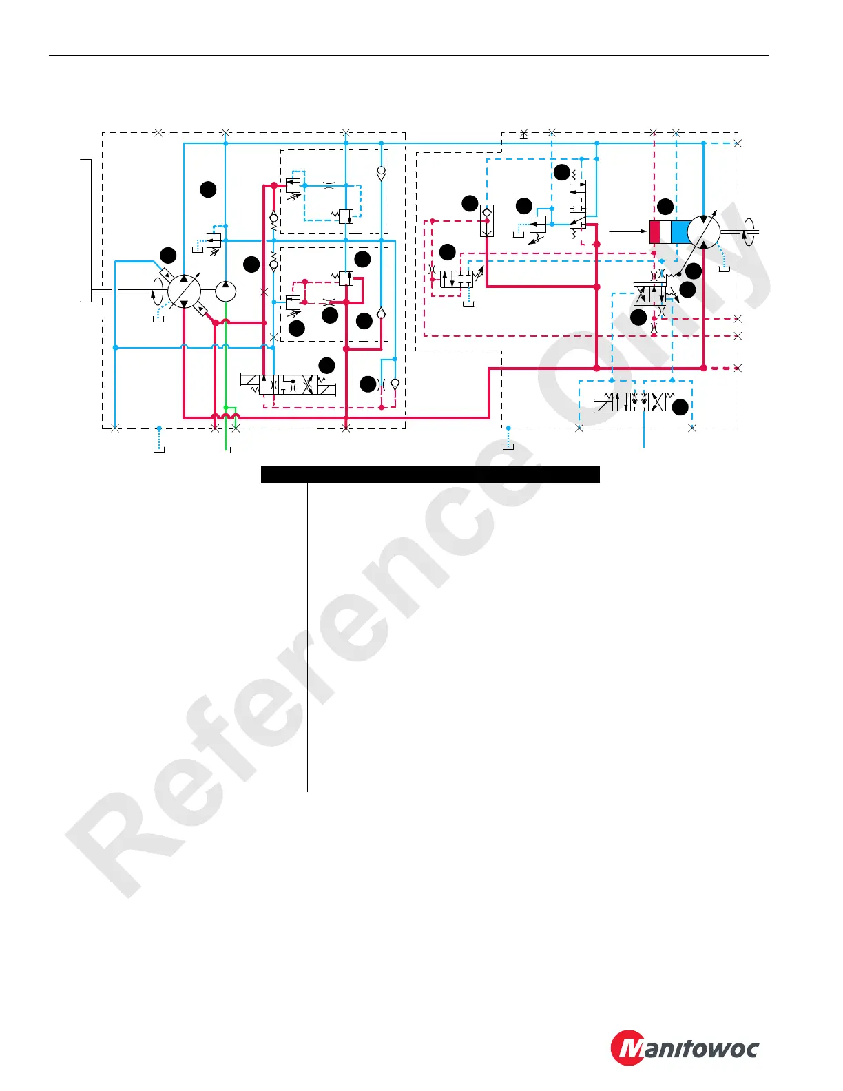
FIGURE 1-11
(340 psi)
23 bar
T2
T3
A
Max.
P
u
m
p
D
r
iv
e
B
B
A
A
DC
EGFD
Output
Input
Pump
Motor
B
A
M8
M7
M3M4M6
L2
M9
M2
M5
M1
11
4
6
18
13
5
10
9
15
14
7
16
12
17
2
1
8
3
Disp.
T1
Item Description
1
Pressure-Limiting Relief Valve
2
Servo Check Valve
3
Displacement Control Valve
4
Servo Control Cylinder
5
System-Relief Valve
6
Charge Pump Relief Valve
7
Charge Flow Make-up Check Valve
8
Flow Control Orifice
9
Flow Restrictor
10
Programmable Controller (PC) Servo Valve
11
Pressure-Control Pilot (PCP) Valve
12
Shuttle Valve
13
Servo Cylinder
14
Adjustable Valve Spring
15
Valve Spring
16
Pressure-Compensating Override (PCOR) valve
17
Control Valve
18
Relief Valve
 Loading...


