Manitowoc Published 07-19-16, Control # 249-01 1-25
2250 SERVICE/MAINTENANCE MANUAL INTRODUCTION
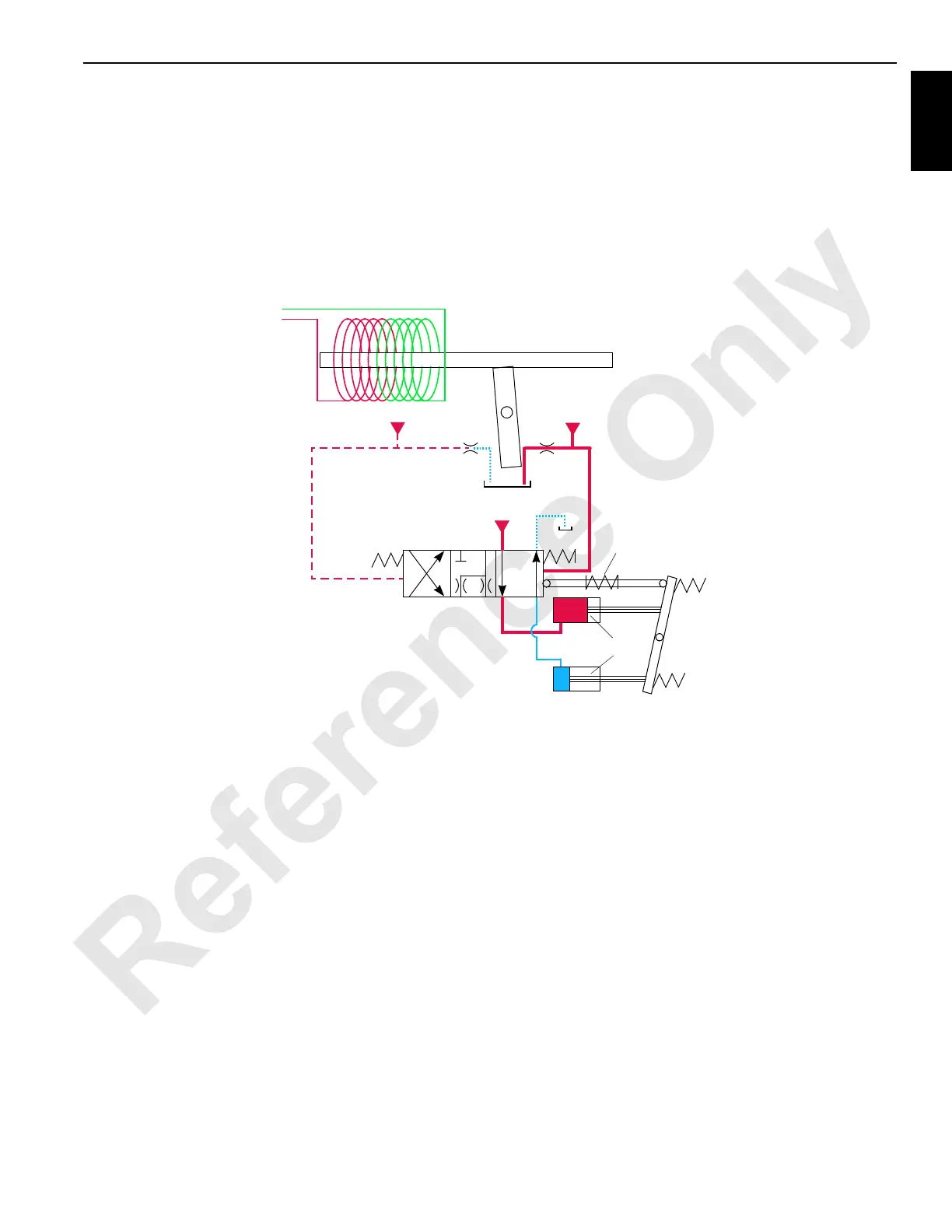
supplied pressure to perform the shifting operation. Servo
control fluid is supplied from the high-pressure line of motor
port A or B and shifts the shuttle valve and the servo control
valve before entering the servo cylinder.
Continuous changing of the closed-loop fluid occurs through
leakage in the pumps, motors, and loop-flushing valves.
Motor case fluid drainage lubricates the motor and provides
a recirculation of hydraulic fluid to control the heat in the
closed-loop system.
The loop-flushing (purge) system consists of a control valve
(17) and a relief valve (18). If the system pressure is above
14 bar (200 psi), the loop-flushing system removes 15 L/min
(4 gpm) of hot fluid from the system for added cooling. If
system pressure is under 14 bar (200 psi), the loop-flushing
system is disabled.
Swashplate
Servo Pistons
Pilot Pressure
Orifice
RF-02
Port
Modulation
Orifice
Port
Spring
Control Voltage
Armature
Spool
Pilot Pressure
Pilot Pressure
Spool
Spring
from Controller
FIGURE 1-10
 Loading...


