Manitowoc Published 07-19-16, Control # 249-01 1-67
2250 SERVICE/MAINTENANCE MANUAL INTRODUCTION
signal is sent to the PC. The PC sends a 12 V output signal
to the auxiliary system’s disable-relief valve HS-12 that
adjusts system pressure to 276 bar (4,000 psi).
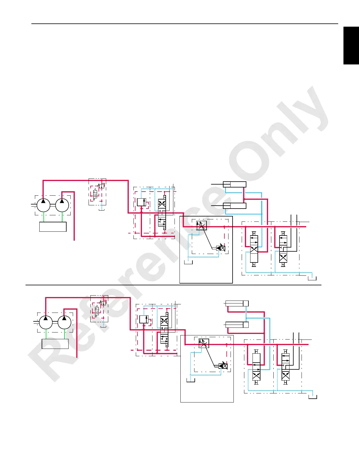
The left crawler frame pins solenoid HS-2 is enabled by the
PC to shift the solenoid valve in the engage position.
Hydraulic fluid enters the upper accessory valve and flows
through the variable output control valve HS-20 and
hydraulic quick disconnect to the lower accessory valve.
Hydraulic fluid exits the valve assembly and flows to the
piston end of the left crawler frame pin cylinders, engaging
the cylinders, to connect the left crawler frame with the
crawler frame. Fluid from the rod end of the cylinders flows
back through the valve assembly through the hydraulic quick
disconnect and to the tank.
When the power button or left crawler frame pins switch is
released, the PC sends a 0 V output to shift the spool of
solenoid HS-2 to the center position.
Crawler Frame Pins Disengage
When the power button is pressed and the left crawler frame
pins switch is held in the UP (disengage) position, an input
signal is sent to the PC. The PC sends a 12 V output signal
to the auxiliary system’s disable-relief valve HS-12 that
adjusts the system pressure to 276 bar (4,000 psi).
The left crawler frame pins solenoid HS-3 is enabled by the
PC to shift the solenoid valve in the disengage position.
Hydraulic fluid exits the valve assembly and flows to the rod
end of the left crawler frame pin cylinders, disengaging the
pins from the crawler frame. Fluid from the piston end of the
cylinders flows through the valve assembly through the
hydraulic quick disconnect and to the tank.
When the power button or left crawler frame pins switch is
released, the PC sends a 0 V output to shift the spool of
solenoid HS-3 to the center position.
Left Crawler Frame Pins Engage
M104194
Auxiliary Pump
Fan Pump
To F a n
Circuit
Upper Accessory Valve
HS-2
HS-3
Lower Accessory Valve
x
Left Crawler Frame Pins Disengage
M104195
Auxiliary Pump
Fan Pump
To F an
Circuit
Upper Accessory Valve
HS-2
HS-3
Lower Accessory Valve
x
Variable Output Valve
Variable Output Valve
HS-13
HS-14
HS-13
HS-14
Suction
Manifold
Suction
Manifold
FIGURE 1-40
0 to 57 L/min (0 to15 gpm)
0 to 57 L/min (0 to15 gpm)
Valve
Disable-Relief
Auxiliary System
HS12
Valve
Disable-Relief
Auxiliary System
HS12
 Loading...


