Manitowoc Published 07-19-16, Control # 249-01 3-25
2250 SERVICE/MAINTENANCE MANUAL ELECTRICAL SYSTEM
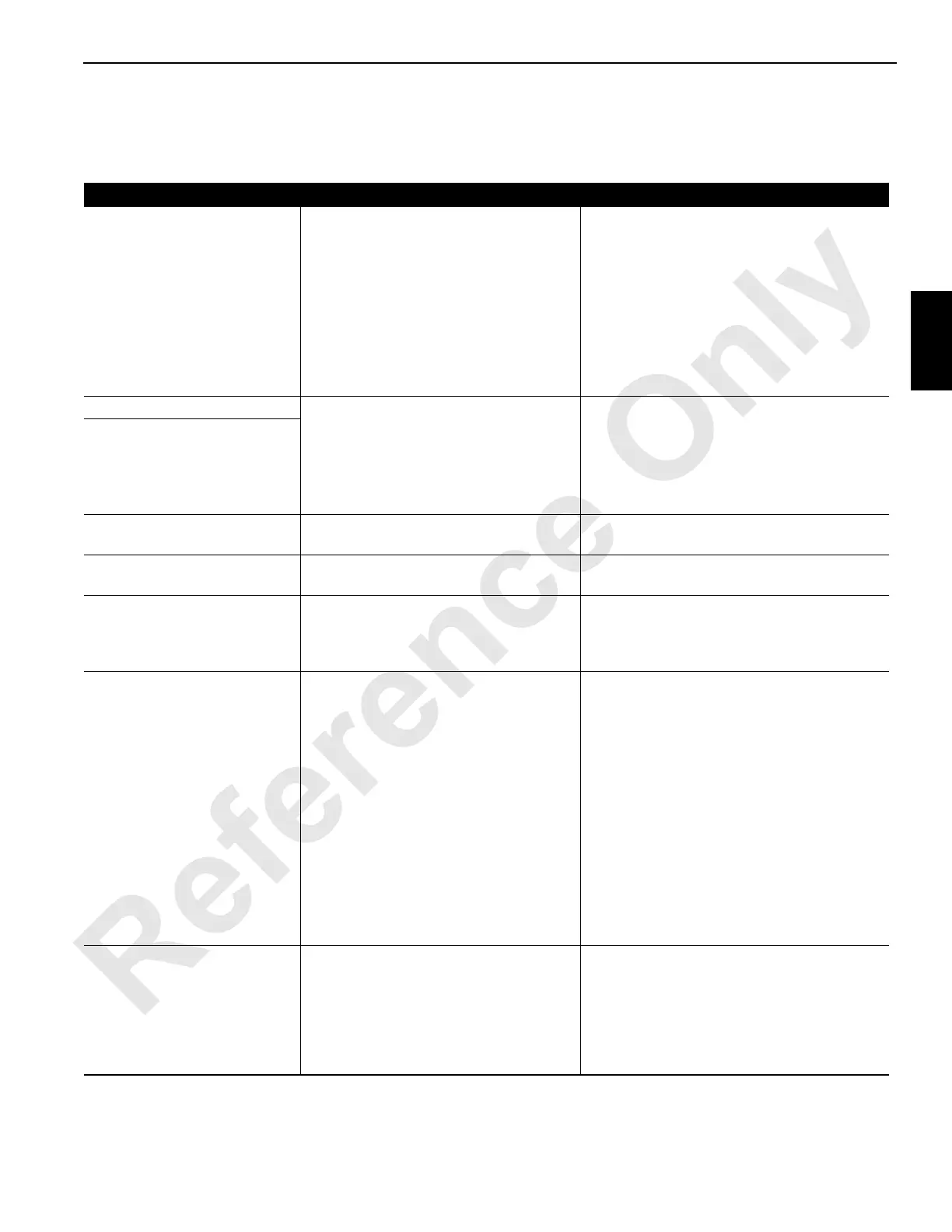
Table 3-4. System Faults
Listed below are the faults that turn on the system fault alert (red light and beeper) in the operator’s cab. When the alert comes
on, scroll to SYSTEM FAULT group of the digital display to determine which fault has been reached. Take corrective action.
Display Reading Cause of Fault Function Response
PUMP 1 CHARGE PRESS Low charge pressure at the load drum
pump.
The load drum brake applies, and the pump
strokes to the neutral position to stop the load
drum. If a drop in charge pressure is
intermittent, operation may be resumed once
the load drum control handle is returned to the
OFF position.
Verify that the cause of the fault is low
pressure and correct the cause as soon as
possible. If the pressure is correct, replace the
pressure sender.
BOOM ANGLE SENDER Sender output voltage 0.0 Volts or above
9.7 Volts.
All functions are operable. The machine level
or boom and luffing jib angle displays will not
be correct. Correct the cause of the sender
fault as soon as possible.
Neither fault is active when the crane is
operated in Setup mode.
* LUFF JIB ANGLE SENDER
LOW AIR PRESSURE Manifold air pressure below 6,2 bar
(90 psi).
If air pressure continues to drop, the load drum
park brakes will apply.
HYD TANK LEVEL Less than 75% level. Stop and check the oil level—fill tank
(reservoir).
LOAD PIN Zero (0) output voltage from the pin. The MAX-ER counterweight stops and
remains in the last position, and the boom
hoist stops and is inoperable in the up
direction.
MOTION A deselected drum turns. If a deselected load drum moves, all drum
brakes and clutches apply, and the pumps
shift to the neutral position to stop all load
drums.
If a selected load drum rotates down when the
handle is in the UP or NEUTRAL position, all
drum brakes and clutches apply and the
pumps shift to the NEUTRAL position to stop
all load drums.
If a deselected boom or luffing hoist drum
moves, the brakes apply and the pumps shift
to the NEUTRAL position to stop both hoists.
Stop and restart the engine to the correct fault
(reboot programmable controller).
* MAX-ER SYSTEM One of the three MAX-ER transducers not
in operating range of 0.6 to 9 Volts.
The differential pressure between the left/
right side strap cylinders is 83 bar
(1,200 psi).
The counterweight tray level is over 3° in
the right or left direction.
The MAX-ER counterweight stops and
remains in the last position.
Check and replace the faulty transducer(s).
Check the hydraulic system and repair.
Level the counterweight tray.
 Loading...


