Manitowoc Published 09-09-16, Control # 229-09 2-33
MLC650 SERVICE/MAINTENANCE MANUAL HYDRAULIC SYSTEM
6. Move the swing handle fully right.
7. At the Swing Diagnostic screen, verify the swing speed
is within the limits of Table 2-1
.
8. Return the swing handle to the center and allow the
rotating bed to come to a stop.
9. Shut off the engine.
Pressure Transducer Test
The pressure transducer test calculates the zero-pressure
output level for each pressure transducer. It is only
necessary to perform this procedure at the specified
intervals or when the following events occur:
• A new pressure transducer is installed.
• A new control module that monitors pressure
transducers is installed.
• Control software is updated.
• Pressure readings are in error.
NOTE: Be aware that if there is any residual pressure in
the system during the calibration process, the
display pressure reading in the cab may not reflect
actual system pressure.
To test the pressure transducers, perform the following
procedure.
1. Stop the engine and turn the ignition switch to the RUN
position.
2. At the Main display, navigate to the Hydraulic Test
screen and select the Pressure Transducer Test
(Figure 2-30
). See the MLC650 Main Display Operation
F2267 for detailed instructions on how to navigate to the
screen and run the test.
3. When the pressure transducer test completes, verify no
pressure transducer icons are highlighted in red. If any
pressure transducer icons appear in red, troubleshoot
the corresponding transducers to determine the fault
cause.
NOTE: The cause of a failed pressure transducer test or
faulty display pressure reading may not be the
pressure transducer. The cause of the fault could
be trapped air or hydraulic pressure in the system
during the pressure transducer test.
Controls Calibration
Controls calibration calculates the pump threshold command
level for the following functions:
• Drums
• Swing
• Travel
• VPC tray and beam
Perform this calibration when:
• A new pump, motor, or sensor is installed
• Control software is updated
• A new control module is installed
• Operation indicates that the threshold is in error:
- Excessive handle motion or time is required to
initiate motion.
- The inability to start motion smoothly is detected.
Perform the following procedure for the controls calibration.
1. Apply all park brakes using the switches on the control
console.
2. Start and run the engine at high idle.
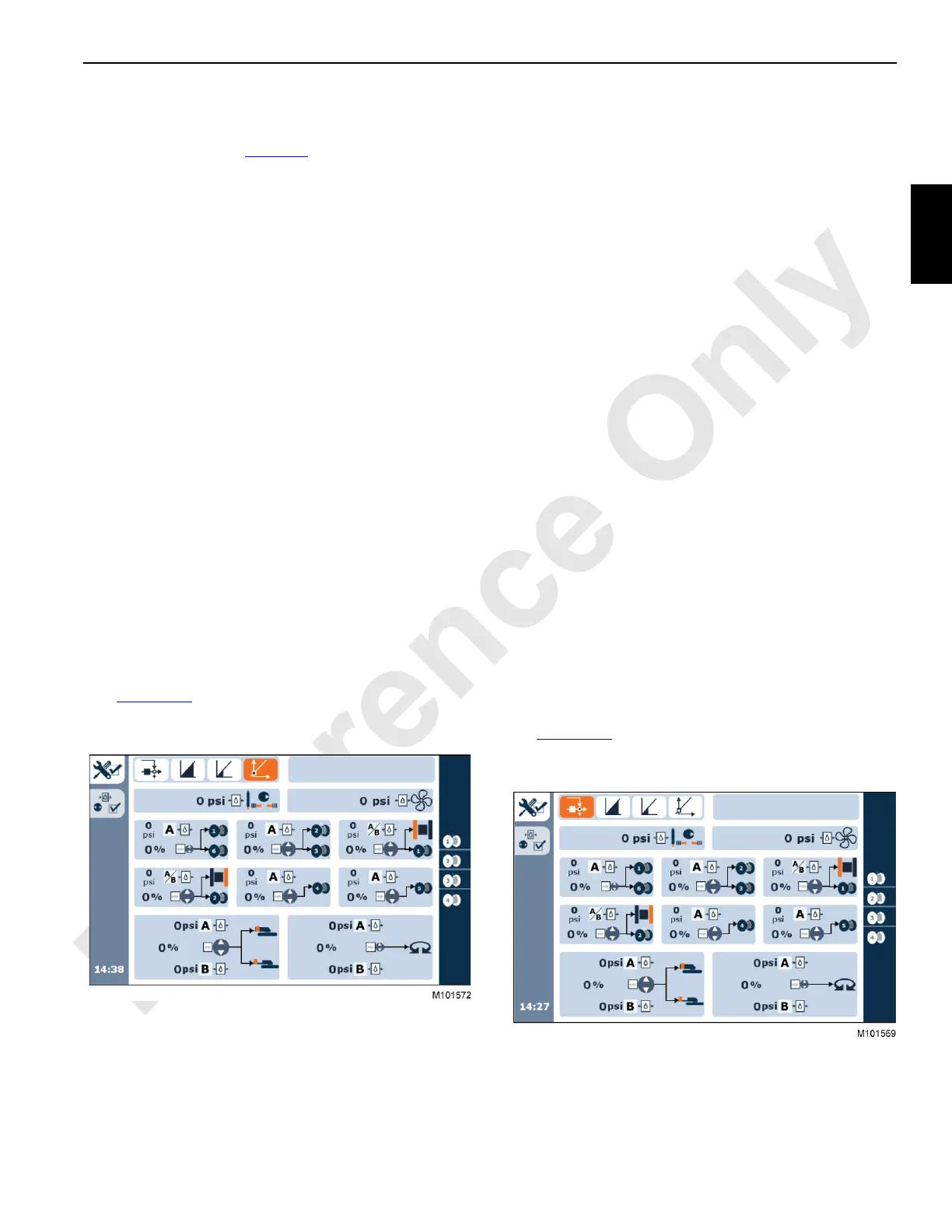
3. At the Main display, navigate to the Hydraulic Test
screen and start the Controls Calibration Test
(Figure 2-31
). See the MLC650 Main Display Operation
F2267 for detailed instructions on how to navigate to the
screen and run the test.
4. Verify no pump icons are highlighted in red.
Troubleshoot failed circuits to determine the fault cause.